A right-angle RJ45 MagJack is the standard choice when you need Ethernet port space, shield performance, and integrated isolation magnetics in one board-mounted part. It is especially useful for compact enclosures, panel-facing ports, industrial devices, and designs where the Ethernet PHY needs a clean, short path to the connector.
For hardware engineers and procurement specialists, selecting the correct Right Angle RJ45 Magjack is a critical decision that impacts both PCB layout and supply chain stability. These integrated magnetic components act as the vital bridge between your Ethernet PHY and the network interface, requiring stringent impedance matching, EMI suppression, and precise footprint planning.
1. What Is a Right Angle RJ45 MagJack?
A Right Angle RJ45 Magjack is an Ethernet connector featuring integrated isolation transformers and common-mode chokes inside the housing. Mounted parallel to the PCB (at a 90-degree angle), it provides necessary signal conditioning, EMI filtering, and high-voltage isolation (minimum 1500Vrms) while saving critical board space in network device enclosures.
A right-angle RJ45 MagJack is an RJ45 connector with integrated magnetics and a PCB mount orientation that exits horizontally from the board. In other words, it combines the modular jack and the isolation magnetics into a single connector assembly. This architecture is widely used in Ethernet hardware because it reduces component count, simplifies routing, and helps fit ports into compact front-panel layouts.
By combining the physical RJ45 port and the magnetic circuitry into a single module, engineers reduce the Bill of Materials (BOM) count and simplify the PCB routing. These components are primarily Through-Hole Technology (THT) and are heavily utilized in enterprise networking, telecommunications, and industrial control systems.
2. Internal Magnetics: Connecting to the Ethernet PHY
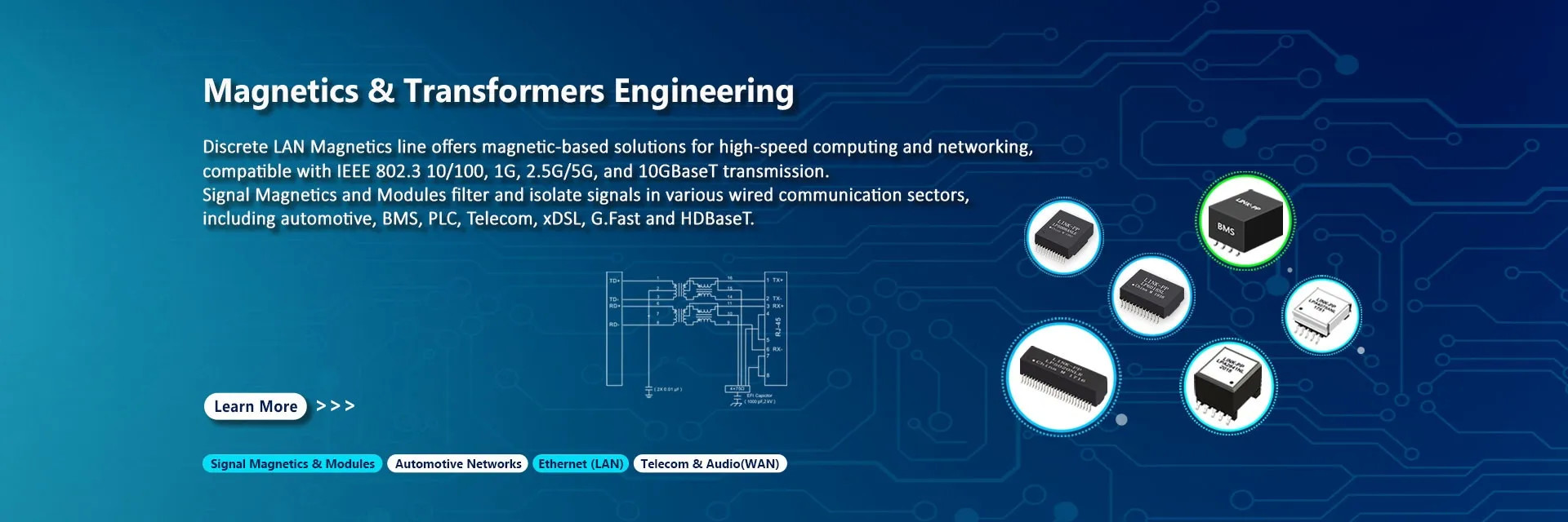
The internal magnetics of an RJ45 Magjack consist of isolation transformers and chokes tailored to match a specific Ethernet PHY chip. The correct selection depends on the PHY’s turn ratio requirements (e.g., 1CT:1CT) and center tap configuration (tied to VDD or Ground) to ensure optimal signal integrity and negotiate a successful network link.
The magnetics inside a MagJack sit between the Ethernet PHY and the cable side of the interface. Their job is to provide signal coupling and isolation while helping the system meet EMC and transient-immunity expectations. TI’s design guidance specifically recommends magnetics that include an isolation transformer and an integrated common-mode choke to reduce EMI, and it notes that board space can be saved by using an RJ-45 with integrated magnetics.
For PCB designers, the key idea is simple: keep the PHY-side routing short, clean, and symmetric. When designing space-constrained PCBs, the right angle orientation provides distinct mechanical benefits. It allows the Ethernet port to sit flush against the edge of a 1U server chassis or an industrial DIN-rail enclosure. By shifting the transformers inside the connector housing, designers reclaim significant PCB real estate that would otherwise be occupied by discrete magnetic modules, allowing for denser routing near the PHY chip.
RJ45 MagJack vs. Standard RJ45 Connector
Understanding the distinction is vital for junior engineers and buyers to avoid catastrophic design failures:
Standard RJ45: A purely mechanical, passive connector made of plastic and metal pins. It offers no electrical isolation or signal conditioning. Requires discrete external transformers on the PCB.
RJ45 Magjack: An active electro-mechanical assembly. It contains integrated coils that provide galvanic isolation, impedance matching, and EMI noise filtering directly at the port edge.
3. Key Specifications to Compare Before Buying & The PCB Footprint Trap
Before purchasing an RJ45 Magjack, buyers must verify the speed rating (10/100 to 10G), PoE capability, shield EMI tabs, LED configurations, and exact footprint dimensions. The biggest sourcing risk is the "Footprint Trap," as mechanical pinouts vary drastically between manufacturers like Pulse, Bel, and LINK-PP.
To successfully specify a Magjack, cross-reference the following technical parameters:
Specification
Technical Details & Considerations
Speed Rating
10/100Base-T, 1000Base-T (Gigabit), 2.5G, 5G, or 10GBase-T. Higher speeds require tighter return loss and crosstalk tolerances.
PoE Support
Non-PoE, PoE (15W), PoE+ (30W), or PoE++ (up to 90W IEEE 802.3bt). Dictates internal wire gauge.
LED Options
Typically Left/Right configurations (e.g., Green/Yellow). Forward voltage usually 1.8~2.6V at 20mA.
EMI Shielding
Presence of EMI spring tabs on the metal housing to ground the connector to the chassis bezel.
PCB Footprint Trap: Avoiding Costly Layout Mistakes
The PCB Footprint Trap: Unlike standard SMD resistors, Magjacks are highly proprietary. Shield grounding tabs and plastic alignment pegs can vary by 0.5mm to 2mm across brands. Always design a "Universal Footprint" on your PCB that accommodates at least two tier-1 manufacturers to prevent manufacturing halts during component shortages.
The most expensive mistake is approving a connector before confirming the land pattern and keepout geometry. Right-angle MagJacks often need careful matching between the mechanical shell, panel ground tabs, PCB ground tabs, LED pin positions, and enclosure cutout. If you lock the PCB first and the connector later, you can end up with a port that does not fit the case or a shield path that is electrically poor. TI’s layout notes and TE’s drawing/CAD availability both reinforce the need to design from the exact part number, not from the catalog family name.
4. PoE Thermal Management in Right Angle Magjacks
Passing high DC bias current (up to 90W via IEEE 802.3bt) through a Magjack causes resistive heating in the internal coils. Effective thermal management requires selecting Magjacks with thicker copper wire gauges and premium ferrite cores to prevent magnetic saturation and thermal runaway during heavy PoE loads.
PoE changes the design conversation because the connector is no longer carrying only data; it is part of a power-delivery path. The IEEE PoE family has evolved from 802.3af to 802.3at and 802.3bt, with increasing delivered power levels and higher thermal demands on the system. Ethernet Alliance materials describe PoE certification around these standards, and 802.3bt expands power delivery further for higher-power use cases.
From a board-design standpoint, that means the MagJack area deserves more attention than a low-power data-only port. Good practice is to preserve copper for heat spreading, keep the shield grounding robust, and avoid crowding hot components near the connector. Higher PoE classes make placement, airflow, and copper continuity more important, especially in compact enclosures. That is an engineering inference from the power levels and EMC requirements described in the PoE and Ethernet layout references.
5. Procurement Strategy: Pricing, Lead Times, and Sourcing
Right Angle RJ45 Magjack procurement requires balancing cost, lead times (typically 4–12 weeks), and second-sourcing. Pricing ranges from $0.45 for basic 10/100 modules in high volume, up to $9.00+ for 10G PoE++ models. Establishing a direct cross-reference with Tier-1 Asian suppliers can reduce BOM costs by 30-50%.
Because these are complex assemblies involving manual coil winding and specialized ferrite cores, they are highly susceptible to supply chain shocks. OEM procurement teams should adopt the following strategies:
Drop Unnecessary Features: If the enclosure hides the port, removing integrated LEDs can reduce the unit price by $0.10–$0.20.
Dual-Sourcing: For every premium US/EU brand specified (e.g., Pulse Electronics or Würth Elektronik), validate an equivalent drop-in replacement from a specialized manufacturer like LINK-PP.
Monitor Lead Times: While standard 1000Base-T parts are stable, high-power PoE++ and 10G Magjacks can experience lead time spikes up to 24 weeks.
A strong procurement workflow is:
lock the PHY speed target,
confirm PoE class,
confirm port orientation and profile,
verify shield grounding strategy,
request footprint/CAD,
sample before tooling.
6. Common Applications for Right Angle RJ45 MagJack
Right-angle RJ45 MagJacks are common in routers, switches, industrial controllers, embedded systems, gateways, and communication devices.
The right angle format is particularly dominant in:
Networking Equipment: Hubs, switches, and ADSL modems where multiple ports are stacked horizontally.
Industrial Control: DIN-rail mounted PLCs and motor controllers requiring robust, isolated Ethernet connectivity.
Embedded Systems: Single-board computers (SBCs) and edge AI gateways where vertical height is strictly limited by the enclosure.
7. FAQ About Right Angle RJ45 MagJack Selection
Q1: What does “integrated magnetics” mean?
A: It means the Ethernet isolation transformer and related magnetic functions are built into the RJ45 connector assembly, instead of being placed on a separate transformer module.
Q2: Are Right Angle RJ45 Magjack footprints standard across brands?
A: No. While the RJ45 plug interface is standardized by IEC 60603-7, the PCB mounting pins, grounding tabs, and alignment pegs vary by manufacturer. Always cross-reference the mechanical drawing.
Q3: Do I need a shielded MagJack for every design?
A: No, but shielded parts are often preferred in industrial or noisy environments because they improve EMC margin and help with chassis grounding strategy. TE and TI both show shielded connector recommendations in Ethernet-oriented designs.
Q4: How thick should the gold plating be on the contact pins?
A: For standard commercial use, specify a minimum of 6 micro-inches (6µ") of hard gold plating. For industrial environments subject to vibration or moisture, upgrade to 15µ" or 30µ" to prevent oxidation and ensure reliable mating cycles.
Q5: What is the standard soldering profile for these connectors?
A: The vast majority are Through-Hole (THT) components designed for wave soldering. Ensure the datasheet guarantees a peak wave solder tip temperature of 265°C for a maximum of 5 seconds.
Q6: Is PoE always supported?
A: No. PoE support is part-specific. The connector, magnetics, PCB copper, and surrounding power path all need to be suitable for the target PoE class. IEEE PoE levels differ significantly across 802.3af, 802.3at, and 802.3bt.
Q7: Why do some parts have LEDs?
A: LEDs give link/activity feedback at the port. TE’s RJ45 portfolio includes connector options with LED indicators, which is useful for switches, gateways, and serviceable equipment.
8. How to Choose the Best Right Angle RJ45 MagJack for Your Project
Choosing the best Magjack requires aligning the electrical schematic with the PHY, ensuring the mechanical footprint supports dual-sourcing, and verifying thermal limits for PoE. Use a structured checklist to bridge the gap between engineering requirements and procurement realities.
Expert Decision Checklist for Engineers and Buyers:
Verify PHY Compatibility: Confirm the turn ratio (e.g., 1CT:1CT) and center tap wiring schematic matches your specific Ethernet controller datasheet.
Design for Alternatives: Draft your PCB footprint to accommodate the primary choice and at least one secondary cross-reference brand.
Assess Environmental Needs: Select the operating temperature range (Commercial 0°C to +70°C vs. Industrial -40°C to +85°C) based on the final deployment environment.
Confirm Isolation Specs: Ensure the Hipot isolation meets IEEE 802.3 requirements (minimum 1500Vrms) to protect the main board from surges.
Audit the Plating and Housing: Specify UL94V-0 rated thermoplastic housing and verify the gold plating thickness matches the expected lifecycle of the product.
Expert Tips for Specifying Your RJ45 Magjack
Use this checklist before releasing the BOM:
Confirm the Ethernet speed class: 10/100, 1G, or 2.5G.
Confirm PoE level and thermal margin.
Confirm right-angle PCB orientation and enclosure clearance.
Confirm shielded vs. unshielded construction.
Confirm LED presence and pin mapping.
Confirm the exact footprint, tab count, and ground strategy from the drawing.
Confirm supplier availability and whether the part is active or legacy.
If you are designing for industrial reliability, prioritize a shielded MagJack with integrated magnetics, strong grounding, and a footprint validated by CAD. If you are designing for compact consumer hardware, prioritize low-profile geometry and front-panel fit first, then verify EMI and PoE performance. TI’s layout recommendations and TE’s product families support that order of decision-making.
A right-angle RJ45 MagJack is not just a connector. It is a PCB interface choice that affects EMI, isolation, enclosure fit, and production risk. The safest sourcing approach is to select the exact part number early, validate the footprint and shield geometry, and make PoE and grounding part of the design review instead of late-stage fixes. That is the difference between a clean Ethernet design and a costly board re-spin.
About the Author: This guide is compiled by B2B electronics procurement specialists and hardware layout experts, leveraging decades of experience in BOM optimization, cross-referencing, and global supply chain management for passive and electro-mechanical components.