



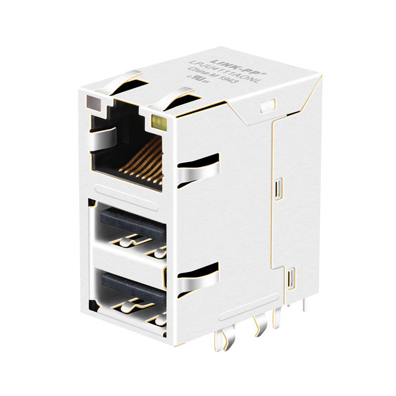
Product Details
Place of Origin: China
Brand Name: LINK-PP
Certification: UL File E484635; RoHS 2011/65/EU
Model Number: HY981160C
Document: LPJU4111AONL.pdf
Payment & Shipping Terms
Minimum Order Quantity: 50/500/1000/60K
Price: $0.55-$1.2
Packaging Details: Tray
Delivery Time: Stock
Payment Terms: TT,NET30/60/90 Days
Supply Ability: 180K/Month
Reference Part Number: |
HanRun HY981160C |
Interface: |
RJ45 (8P8C) + Dual USB A |
Ethernet Speed: |
10/100 BASE-T |
Dimensions: |
25.88 X 16.92 X 29.40 Mm |
LINK-PP Part Number: |
LPJU4111AONL |
Magnetics Turns Ratio: |
1CT:1CT (±5%) |
Mounting: |
Through-Hole 90° (THT) |
Optical Status: |
Orange-Green / Yellow |
PoE Standard: |
Non-PoE |
Isolation HiPot: |
1500 Vrms MIN |
Reference Part Number: |
HanRun HY981160C |
Interface: |
RJ45 (8P8C) + Dual USB A |
Ethernet Speed: |
10/100 BASE-T |
Dimensions: |
25.88 X 16.92 X 29.40 Mm |
LINK-PP Part Number: |
LPJU4111AONL |
Magnetics Turns Ratio: |
1CT:1CT (±5%) |
Mounting: |
Through-Hole 90° (THT) |
Optical Status: |
Orange-Green / Yellow |
PoE Standard: |
Non-PoE |
Isolation HiPot: |
1500 Vrms MIN |
The HY981160C is a high-density, 3-in-1 hybrid I/O interface that integrates a single-port 10/100BASE-T Fast Ethernet RJ45 MagJack and two stacked USB 2.0 Type-A Female ports into a single vertical right-angle through-hole package. Measuring 25.88 mm (L) × 16.92 mm (W) × 29.40 mm (H), it reduces PCB front-panel horizontal edge width by over 65%.
Internally equipped with 1CT:1CT magnetic isolation transformers, dedicated internal metal shielding between Ethernet and USB signal cavities, and Left Orange/Green & Right Yellow status LEDs, it delivers 1500 Vrms dielectric isolation.
| LINK-PP part number | LPJU4111AONL |
|---|---|
| Reference part number | HanRun HY981160C |
| Interface | One RJ45 jack with integrated magnetics and two stacked USB receptacles |
| Ethernet | 10/100BASE-T; non-PoE application |
| Mounting | Right-angle side entry, through-hole; tab up |
| LEDs | Left orange/green; right yellow, viewed from the mating face |
| Operating temperature | 0 °C to +70 °C |
| Isolation | 1500 Vrms, PHY side to line side |
This stacked RJ45 and dual USB connector brings three front-panel interfaces together in one shielded package. The integrated Ethernet magnetics include transformers and common-mode chokes, with a termination network shown in the schematic. It is suited to designs such as LAN-on-motherboard, network equipment, embedded boards and Ethernet control systems, subject to application qualification.
It is a connector assembly, not a USB-to-Ethernet adapter. The Ethernet and USB interfaces connect separately to the host board; a suitable Ethernet PHY, USB controller and board-level power and protection circuitry are required.
Electrical measurements are specified at 25 °C unless otherwise stated.
| Parameter | Specification |
|---|---|
| Ethernet connector | 8P8C RJ45, integrated 10/100BASE-T magnetics |
| Turns ratio, TX and RX | 1CT:1CT ±5% |
| Open-circuit inductance | 350 µH minimum at 100 kHz, 0.1 V and 8 mA DC bias |
| Insertion loss | -1.2 dB maximum, 1–100 MHz, as stated in the drawing |
| Return loss | -16 dB at 1–30 MHz; -12 dB at 30–60 MHz; -10 dB at 60–80 MHz; -8 dB at 80–100 MHz; drawing specifies these as minimum values |
| Crosstalk and common-mode rejection | -30 dB minimum, 1–100 MHz, each as stated in the drawing |
| Isolation | 1500 Vrms, PHY side to line side |
| Housing / contacts / shield | Black PBT, UL 94V-0 / phosphor bronze / nickel-plated copper alloy |
| Contact plating | Gold, 6 micro-inches minimum in contact area |
| Soldering | Wave solder tip: 250 °C for 5 seconds, as specified in drawing |
| Compliance note | Drawing states UL file E484635 and RoHS 2011/65/EU; request current documentation for the ordered part. |
The mechanical drawing shows a nominal body width of 16.92 mm, height of 29.4 mm and depth of 25.88 mm; 19.72 mm is indicated across the projecting side features. The suggested panel opening is 18.08 × 30.43 mm. Check drawing tolerances, spring features and panel clearance against the enclosure before release.
The recommended PCB layout is shown in top view: six Ø0.90 mm holes for P1–P6, four Ø1.02 mm holes for P7–P10, eight Ø0.92 mm holes for U1–U8, four Ø2.30 mm holes and four Ø1.70 mm holes for mechanical/shield features. Use the full dimensioned drawing to position the holes and determine fabrication tolerances.
The schematic identifies P2/P3 as TD+/TD−, P1 as TCT, P4/P5 as RD+/RD− and P6 as RCT. The cable-side contacts are labelled J1, J2, J3 and J6 for the transformer signal paths. The drawing shows the left orange/green LED at P9/P10 and the right yellow LED at P7/P8. Verify LED polarity against the schematic and confirm USB pin functions with the manufacturer before connecting the board.
No. The LPJU4111AONL drawing specifies 10/100BASE-T integrated magnetics. Select a separately qualified Gigabit version when 1000BASE-T is required.
LINK-PP lists this part for a non-PoE Ethernet application. For a powered Ethernet design, request a connector specifically specified for the required PoE standard and power level.
No. The ports are separate interfaces in a shared mechanical assembly. The board must supply the appropriate controllers and circuitry.
Compare the top-view footprint, hole sizes and positions, pin assignments, dimensions, mating orientation and panel opening with your existing design. Request the latest drawing and a sample if the component is intended as a replacement.
Contact LINK-PP with the required part number, quantity, target application and delivery location. Ask for current stock, lead time, samples and technical documentation for your project.