



Product Details
Place of Origin: China
Brand Name: LINK-PP
Certification: UL,ROHS,Reach,ISO
Model Number: LPJE160HENL
Document: LPJK2064A9NL.pdf
Payment & Shipping Terms
Minimum Order Quantity: Free Samples Support
Price: $0.35
Packaging Details: 60pcs/tray,840pcs/carton
Delivery Time: 3-5 days
Payment Terms: L/C,D/A,D/P,T/T
Supply Ability: 5KK/Month
Part No.: |
LPJK2064A9NL |
Category: |
RJ45 Connector With Integrated Magnetics |
Compatible Brands: |
Pulse |
Number Of Ports: |
1X1 |
Latch: |
Up |
Data Rate: |
1000Base-T |
PoE: |
PoE |
LED Option: |
With |
EMl Tabs: |
With |
Mounting Type: |
THT |
Solder Type: |
Wave |
Operating Temperature Range: |
0°C To +70°C |
Part No.: |
LPJK2064A9NL |
Category: |
RJ45 Connector With Integrated Magnetics |
Compatible Brands: |
Pulse |
Number Of Ports: |
1X1 |
Latch: |
Up |
Data Rate: |
1000Base-T |
PoE: |
PoE |
LED Option: |
With |
EMl Tabs: |
With |
Mounting Type: |
THT |
Solder Type: |
Wave |
Operating Temperature Range: |
0°C To +70°C |
The LINK-PP LPJK2064A9NL is an industrial-grade, single-port (1x1) Gigabit (1000BASE-T) RJ45 Integrated Connector Module (ICM / Magjack) designed for high-density networking applications requiring Power over Ethernet (PoE). Featuring integrated 1CT:1CT isolation transformers, common-mode filtering, Bob Smith 75Ω termination, multi-contact EMI spring fingers, and dual integrated LEDs, it delivers robust signal integrity and 1500 Vrms isolation in a compact footprint.
| Parameter | Specification | Engineering Benefit |
| Transmission Speed | 1000BASE-T (Gigabit Ethernet) | High-speed throughput for switch/router uplinks |
| PoE Capability | 350 mA Max @ 57 VDC Continuous | Fully compatible with IEEE 802.3af (PoE Type 1) |
| Turns Ratio | 1CT : 1CT ±5% (TX & RX) | Broad compatibility with current/voltage-mode PHYs |
| Open Circuit Inductance (OCL) | 350 µH Min @ 100 kHz, 0.1 V, 8 mA DC Bias | Prevents magnetic core saturation under bias |
| Dielectric Isolation | 1500 Vrms (PHY side to Line side) | Protection against high-voltage surges and ESD |
| Left LED | Bi-color: Green (565 nm) / Yellow (585 nm) | 2-pin antiparallel multi-state activity indicator |
| Right LED | Single Color: Green (565 nm) | Dedicated link/power status indicator |
| Shielding & EMI | SUS 304 Stainless Steel with Spring Fingers | Multi-point chassis ground for low radiated emissions |
| Mounting & Profile | Through-Hole (THT), 32.5 mm depth, Tab-Up | Standard panel cut-out integration |
The following electrical specifications are provided for LPJK2064A9NL at 25°C.
| Electrical Parameter | Specification |
|---|---|
| Turn Ratio | 1CT : 1CT ±5% |
| Open Circuit Inductance (OCL) | 350 μH Min. @ 100 kHz, 0.1 V, 8 mA DC Bias |
| Insertion Loss | -1.2 dB Max. @ 1–100 MHz |
| Return Loss | -16 dB Min. @ 1–30 MHz |
| Return Loss | -12 dB Min. @ 30–60 MHz |
| Return Loss | -10 dB Min. @ 60–80 MHz |
| Return Loss | -8 dB Min. @ 80–100 MHz |
| Crosstalk | -30 dB Min. @ 1–100 MHz |
| Common Mode Rejection | -30 dB Min. @ 1–100 MHz |
| PoE Balanced DC Line Current | 350 mA Max. @ 57 VDC continuous |
| Isolation Voltage | 1500 Vrms, PHY Side to Line Side |
| Operating Temperature | 0°C to +70°C |
These specifications are particularly relevant when qualifying the connector for a Gigabit Ethernet PCB design because they provide the electrical performance criteria needed to evaluate the integrated magnetic interface rather than treating the part as a mechanical RJ45 jack alone.
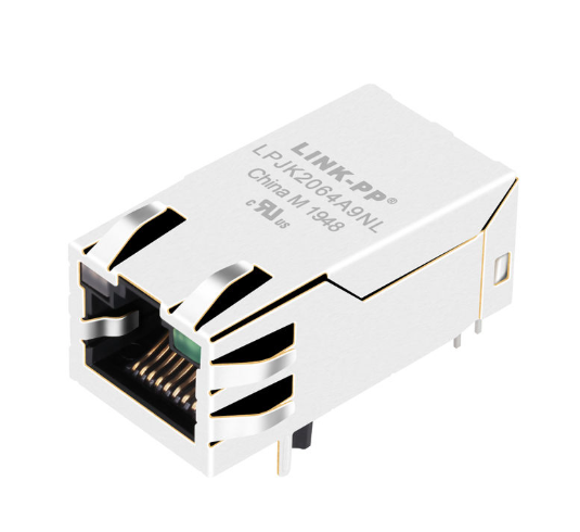
LPJK2064A9NL is a 1×1 1000BASE-T RJ45 connector with integrated magnetics, EMI spring finger, LED indicators and PoE support for Ethernet applications.
The LPJK2064A9NL features a matched 4-channel differential interface for complete 1000BASE-T full-duplex operation, integrated Bob Smith passive termination, and dedicated Power over Ethernet center-tap paths.
PHY Side Connections (Pins 1–12):
PoE DC Injection Pins (Pins 13–16): VC+(Pin 13, Pin 15) and VC−(Pin 14, Pin 16) route power directly through the center taps of the cable-side transformers, rated for 350 mA continuous balanced current.
Integrated Common-Mode & Transient Protection:
LPJK2064A9NL is designed for PoE applications and specifies a maximum continuous balanced DC line current of:350 mA at 57 VDC
The specified line-side current capability should be considered when qualifying the connector for the intended PoE architecture.
The product also provides 1500 Vrms isolation between the PHY side and line side, an important electrical characteristic for isolated Ethernet interfaces.
For a complete PoE implementation, system designers should evaluate the RJ45 magnetic interface together with the PoE PSE/PD circuitry, PHY, protection components, PCB layout, thermal conditions, and applicable IEEE 802.3 requirements.
Important: The 350 mA / 57 VDC specification should not by itself be interpreted as a guaranteed PoE power-class rating. The applicable PoE power level must be determined from the complete product specification and system implementation.
1, Chassis Ground vs. Digital Ground:
Do not directly connect the digital circuit ground (DGND) to the connector’s outer metal shield pins. The LPJK2064A9NL contains an internal 1000 pF/2 kV capacitor that safely couples high-frequency noise from the center tap to chassis shield while maintaining low-frequency DC isolation.
2. Differential Pair Routing:
Ensure all four pairs (MD1±to MD4±) are routed as 100 Ω differential impedance controlled pairs. Keep intra-pair length matching within ±5 mils and minimize layer transitions through vias.
3. PoE Current Traces:
Traces extending from Pins 13, 14, 15, and 16 to your onboard PoE controller or PD bridge must be sized with sufficient trace width (minimum 25–30 mils for 1 oz copper) to handle the continuous 350 mA DC current without thermal elevation.
4. Panel Grounding:
Ensure the perimeter EMI spring fingers maintain consistent 360-degree spring contact against the bare metal front panel bezel to prevent RF leakage at the 125 MHz Ethernet fundamental frequency.
Answer: The LPJK2064A9NL incorporates isolated center-tap DC output lines (Pins 13 to 16) capable of carrying up to 350 mA continuous current at 57 VDC. Standard non-PoE Magjacks tie these center taps internally only to Bob Smith termination resistors, which cannot carry direct current and will burn out if subjected to PoE voltages.
Answer: Pins 19 and 20 are connected to an antiparallel dual-diode pair. To illuminate Green, drive Pin 20 HIGH (1.8 V∼2.6 V) and Pin 19 LOW. To illuminate Yellow, reverse the drive states by driving Pin 19 HIGH and Pin 20 LOW. When both GPIO lines are held at the same logic state, the LED remains unlit.
Answer: Yes. The LPJK2064A9NL utilizes symmetrical 1CT:1CT turns ratios on all four channel transformers. It interfaces seamlessly with voltage-mode PHYs (where center taps terminate to ground via decoupling capacitors) and current-mode PHYs (where center taps are tied to the PHY supply voltage, e.g., +3.3 V or +2.5 V).
Answer: No. The LPJK2064A9NL is rated for a maximum balanced line current of 350 mA continuous at 57 VDC, which aligns with IEEE 802.3af (PoE Type 1, up to 15.4 W). For higher-power PoE+ (600 mA, 30 W) or PoE++ applications, please contact LINK-PP for our upgraded 600 mA/1000 mA magnetic series.