



Product Details
Place of Origin: China
Brand Name: LINK-PP
Certification: UL,ROHS,Reach,ISO
Model Number: LPJD0713BENL
Document: LPJD0713BENL.pdf
Payment & Shipping Terms
Minimum Order Quantity: Free Samples Support
Price: $0.35-$0.7
Packaging Details: Tape & Reel
Delivery Time: 3-5 days
Payment Terms: L/C,D/A,D/P,T/T
Supply Ability: 5KK/Month
Part No.: |
LPJD0713BENL |
Number Of Ports: |
1X1 |
Latch: |
Up |
Data Rate: |
1000Base-T |
PoE: |
Non |
LED Option: |
With |
EMl Tabs: |
Without |
Mounting Type: |
THT |
Solder Type: |
Wave |
Operating Temperature Range: |
0°C To +70°C |
Part No.: |
LPJD0713BENL |
Number Of Ports: |
1X1 |
Latch: |
Up |
Data Rate: |
1000Base-T |
PoE: |
Non |
LED Option: |
With |
EMl Tabs: |
Without |
Mounting Type: |
THT |
Solder Type: |
Wave |
Operating Temperature Range: |
0°C To +70°C |
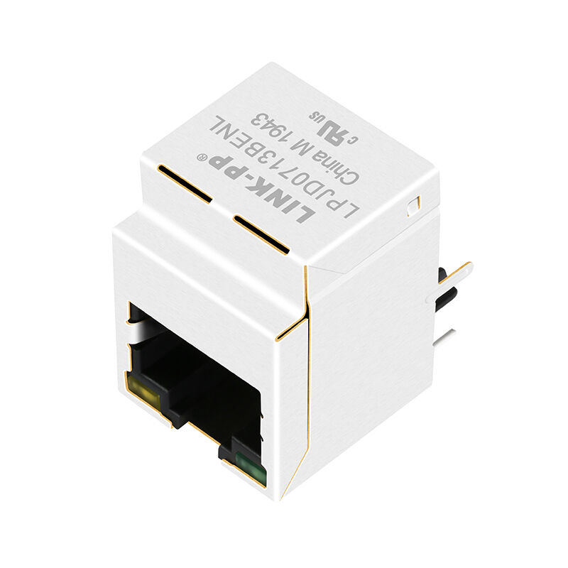
The LINK-PP LPJD0713BENL is an industrial-grade, single-port (1x1) vertical (top-entry / 180° straight) Gigabit Ethernet (1000BASE-T) RJ45 Integrated Connector Module (ICM / Magjack). Designed specifically for space-constrained carrier boards, blade servers, test instrumentation, and DIN-rail industrial PCs where top-access cable mating is required, it integrates 1CT:1CT magnetic isolation transformers, primary-side filtering capacitors, an internal Bob Smith termination network, a metal EMI shield, and dual status LEDs into a compact through-hole profile.
| Parameter | Specification | Engineering Benefit |
|---|---|---|
| Connector Orientation | Vertical / Top-Entry (180° Straight) | Saves PCB edge space; enables direct top-panel cable insertion |
| Ethernet Speed | 1000BASE-T (Gigabit Ethernet) | Full-duplex gigabit compliance per IEEE 802.3 |
| Turns Ratio | 1CT : 1CT ±5% | Symmetrical 1:1 ratio compatible with major Gigabit PHYs |
| Open Circuit Inductance (OCL) | 350 µH Min. (@ 100 kHz, 0.1 V, 8 mA DC Bias) | Prevents core saturation under direct DC unbalance currents |
| Dielectric Isolation (Hipot) | 1500 Vrms Min. (PHY Side to Line Side) | High-voltage transient protection between system and cable |
| Primary-Side Filtering | Built-in 4× 0.01 µF Decoupling Capacitors | Integrated AC ground path; reduces external discrete capacitor count |
| Cable-Side Termination | Integrated Bob Smith (4× 75 Ω + 1000 pF / 2 kV) | Dampens common-mode cable reflections directly to outer shield |
| Left LED | Single-Color: Green (565 nm) | Dedicated Link / Connection status indicator (Pins 13+/14-) |
| Right LED | Single-Color: Yellow (585 nm) | Dedicated Activity / Data transfer indicator (Pins 11+/12-) |
| Mechanical Height | 22.0 ± 0.35 mm Total Height | Standardized profile for vertical modular board-to-panel mating |
| Parameter | Test Condition | Specification Limit |
|---|---|---|
| Turns Ratio | 100 kHz, 0.1 V | 1CT : 1CT ±5% |
| Open Circuit Inductance (OCL) | 100 kHz, 0.1 V, 8 mA DC Bias | 350 µH Min. |
| Insertion Loss | 1 ~ 100 MHz | -1.2 dB Max. |
| Return Loss (100 Ω Load) | 1 ~ 30 MHz | -16.0 dB Min. |
| Return Loss (100 Ω Load) | 30 ~ 60 MHz | -12.0 dB Min. |
| Return Loss (100 Ω Load) | 60 ~ 80 MHz | -10.0 dB Min. |
| Return Loss (100 Ω Load) | 80 ~ 100 MHz | -8.0 dB Min. |
| Cross Talk (Near-End) | 1 ~ 100 MHz | -30.0 dB Min. |
| Common Mode Rejection (CMR) | 1 ~ 100 MHz | -30.0 dB Min. |
| Isolation Voltage (Hipot) | 60 Seconds (PHY Side to Line Side) | 1500 Vrms Min. |
| Operating Temperature Range | Continuous Ambient | 0°C to +70°C |
The LPJD0713BENL maps 4 full Gigabit differential pairs with integrated magnetic coupling, internal primary decoupling, and high-voltage line-side ESD/common-mode return paths.
PHY SIDE (PCB CONNECTIONS)                         LINE SIDE (RJ45 CONNECTOR)
  TD0+ (Pin 1) ───┐       ┌─── 0.01uF ─── VCC (Pin 9)
                  ) 1CT   ( 1CT
  TD0- (Pin 2) ───┴───────┴─── 75 Ω ─────┐
                                         │
  TD1+ (Pin 3) ───┐       ┌─── 0.01uF ───┤
                  ) 1CT   ( 1CT          │
  TD1- (Pin 6) ───┴───────┴─── 75 Ω ─────┼──── J1 (MX0+) / J2 (MX0-)
                                         │──── J3 (MX1+) / J6 (MX1-)
  TD2+ (Pin 4) ───┐       ┌─── 0.01uF ───┤──── J4 (MX2+) / J5 (MX2-)
                  ) 1CT   ( 1CT          │──── J7 (MX3+) / J8 (MX3-)
  TD2- (Pin 5) ───┴───────┴─── 75 Ω ─────┤
                                         │
  TD3+ (Pin 7) ───┐       ┌─── 0.01uF ───┘
                  ) 1CT   ( 1CT          │
  TD3- (Pin 8) ───┴───────┴─── 75 Ω ─────┘
                                         │
                             SHIELD ─────┴── 1000 pF / 2 kV High-Voltage Cap
| Pin # | Pin Name | Direction | Signal Type / Function | RJ45 Mating Contact |
| P1 | TD0+ | Input/Output | Differential Pair 0 Positive | J1 (MX0+) |
| P2 | TD0- | Input/Output | Differential Pair 0 Negative | J2 (MX0-) |
| P3 | TD1+ | Input/Output | Differential Pair 1 Positive | J3 (MX1+) |
| P6 | TD1- | Input/Output | Differential Pair 1 Negative | J6 (MX1-) |
| P4 | TD2+ | Input/Output | Differential Pair 2 Positive | J4 (MX2+) |
| P5 | TD2- | Input/Output | Differential Pair 2 Negative | J5 (MX2-) |
| P7 | TD3+ | Input/Output | Differential Pair 3 Positive | J7 (MX3+) |
| P8 | TD3- | Input/Output | Differential Pair 3 Negative | J8 (MX3-) |
| P9 | VCC | Power / Bias | Primary Center-Tap Bus Coupling (4× 0.01 µF) | Internal bus to PHY supply |
| P10 | GND | Ground | Primary Decoupling Reference Ground | System Digital Ground |