



Product Details
Place of Origin: China
Brand Name: LINK-PP
Certification: UL,ROHS,Reach,ISO
Model Number: JXF0-5012NL
Payment & Shipping Terms
Minimum Order Quantity: 40pcs
Price: $1.7
Packaging Details: Tray
Delivery Time: In Stock Ship Within 1-2 weeks
Payment Terms: L/C,D/A,T/T,D/P
Supply Ability: 5KK/Month
Part Number: |
JXF0-5012NL |
Product Family: |
PulseJack JXF0 |
Port Configuration: |
1×1, Single Port |
Data Rate: |
5GBASE-T |
LED Configuration: |
Green-Yellow / Green-Yellow |
PoE Configuration: |
4-Pair PoE |
PoE Current: |
900 MA Max. |
PoE Power Rating: |
90 W |
EMI Choke: |
3 W, PHY Side |
EMI Fingers: |
Top & Sides |
Mounting: |
Through Hole |
Assembly: |
Hrough-Hole Reflow Compatible |
Part Number: |
JXF0-5012NL |
Product Family: |
PulseJack JXF0 |
Port Configuration: |
1×1, Single Port |
Data Rate: |
5GBASE-T |
LED Configuration: |
Green-Yellow / Green-Yellow |
PoE Configuration: |
4-Pair PoE |
PoE Current: |
900 MA Max. |
PoE Power Rating: |
90 W |
EMI Choke: |
3 W, PHY Side |
EMI Fingers: |
Top & Sides |
Mounting: |
Through Hole |
Assembly: |
Hrough-Hole Reflow Compatible |
What is the JXF0-5012NL connector and what are its core specifications?
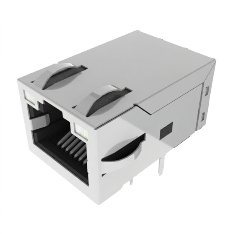
The JXF0-5012NL is a rugged, industrial integrated RJ45 connector (ICM/MagJack). It is specified for 5GBase-T (5 Gbps) high-speed Ethernet and delivers 90W 4-Pair PoE++ power (900 mA @ 57VDC, IEEE 802.3bt compliant). Key specs include an industrial operating temperature of -40°C to +85°C, 2250 VDC galvanic isolation (transformer side), dual Green/Yellow bi-colour LEDs, and a Pin-in-Paste / Through-Hole Reflow (THR) compatible footprint with Top & Sides EMI spring fingers.
The JXF0-5012NL is an industrial-grade, single-port Gigabit PulseJac Integrated Connector Module (ICM) engineered specifically for bandwidth-demanding, high-power embedded applications. Fully supporting 5GBase-T Ethernet speeds under IEEE 802.3 specifications, this connector incorporates internal magnetics, 3-wire PHY-side common mode chokes, and direct high-power termination capable of delivering up to 90W (900mA continuous @ 57VDC over 4 pairs) for IEEE 802.3bt Type 4 PoE++ devices.
Designed for robust deployment in extreme environments, the JXF0-5012NL operates across a -40°C to +85°C temperature range. Its specialized housing and pin construction enable Through-Hole Reflow (THR / Pin-in-Paste) processing, reducing PCB assembly costs by eliminating manual secondary soldering operations while achieving an MSL 1 shelf life and high mechanical retention.
| Parameter | Specification | Standard / Condition |
| Operating Temperature | -40°C to +85°C | Full rated current & bandwidth |
| Storage Temperature | -40°C to +85°C | Unmounted / In Packaging |
| Dielectric Withstand (Isolation) | 2250 VDC / 60 seconds | Primary to Secondary (Transformer only) |
| Flammability Rating | UL 94V-0 or better | Thermoplastic Housing |
| Moisture Sensitivity Level (MSL) | MSL 1 (Unlimited shelf life) | IPC / JEDEC J-STD-020 |
| Safety Compliance | UL 62368-1 (File E216117) | Information/Audio-Video Tech Standard |
| Metric | Frequency Range | Value (Limit) |
| Data Rate | Baseband Ethernet | 5GBase-T (IEEE 802.3) |
| Open Circuit Inductance (OCL) | 100 kHz, 0.1 mA | 180 µH Min (Datasheet listed as 180mH) |
| Insertion Loss (Max) | 1.0 MHz – 125 / 250 MHz | -1.0 dB / -1.5 dB |
| Return Loss (Min) |
1 MHz – 40 MHz 40 MHz – 100 MHz 100 MHz – 250 MHz |
-24 dB -19 dB -14 dB (formula: -20+[12.5×log10(f/40MHz)]) |
| Crosstalk (Typ) |
10 MHz – 125 MHz 125 MHz – 250 MHz |
-30 dB -20 dB |
| Common Mode Rejection (Min) |
10 MHz – 125 MHz 125 MHz – 250/400 MHz |
-35 dB -30 dB / -25 dB |
| EMI Choke Topology | Internal Magnetics | 3-Wire (3W), PHY Side |
| Parameter | Specification | Notes |
| PoE Class Support | IEEE 802.3bt Type 4 (PoE++) | 4-Pair Power Architecture |
| Maximum Current | 900 mA Continuous | Per 2 pairs (Total 1.8A loop) |
| Continuous Power Rating | 90 W @ 57 VDC | Continuous duty rating |
| PoE Dedicated Pins | Pins 15, 16, 17, 18 | Isolated from internal low-voltage PHY paths |
| Component | Material | Plating / Finish |
| Contact Terminals | Phosphor Bronze | 30 µ-inch (0.76 µm) Gold over 30 µ-inch min Nickel |
| Solder Tails | Phosphor Bronze | 100 µ-inch min 100% Matte Tin |
| Shield Shell | Copper Alloy | Nickel Plated with Top & Side Grounding Fingers |
| Recommended PCB Finish | FR4 | HASL (Compatible with ENIG, OSP) |
The JXF0-5012NL integrates 18 functional pins plus 2 mechanical ground retention posts:
PCB Hole Layout (Component Side View):
   [12] [11] (Left LED)                       [14] [13] (Right LED)
       [10] [8]  [6]  [4]  [2]   <- Signal Rows
         [9]  [7]  [5]  [3]  [1]
             [18]  [16]          <- Dedicated 90W PoE Pins
               [17]  [15]
 (Shield Tab)                                         (Shield Tab)
Pins 1–10 (Signal & Center Taps):
Pins 11–14 (Bi-Colour LEDs):
Pins 15–18 (PoE Power Injection Inputs):
Yes. JXF0-5012NL is a 4-pair PoE version rated for 900 mA and 90 W. The manufacturer lists this configuration as 900mA - 90W 4 Pair.
| PoE Parameter | JXF0-5012NL |
|---|---|
| PoE Support | Yes |
| Pair Configuration | 4-Pair |
| Maximum Current | 900 mA |
| Rated Power | 90 W |
| EMI Choke | 3 W, PHY Side |
The 90 W rating is an important distinction from standard non-PoE and lower-power PoE RJ45 interfaces.
The JXF0-5012NL is a PoE-capable RJ45 integrated connector, not a complete PoE power-conversion module.
A complete PoE design still requires the appropriate:
The connector's 90 W capability therefore should not be interpreted as meaning that every system using this component can automatically deliver 90 W to a powered device.
A: Yes. The internal magnetics and transformer ratios (1:1) meet IEEE 802.3 specifications across 1Gbps, 2.5Gbps, and 5Gbps. It will auto-negotiate and operate seamlessly at lower data rates.
A: In pure non-PoE connectors (e.g., JXF0-5010NL), 2250VDC isolation exists entirely between the cable-side RJ45 pins and all PCB-side pins. In JXF0-5012NL, dedicated high-power lines connect directly to center taps for PoE injection (Pins 15–18); hence, high-voltage galvanic breakdown protection is strictly maintained across the transformer signal coils, not through the PoE injection DC paths.
A: Carrying 900mA per pair introduces heavy common-mode DC flux. Placing a 3-wire common mode choke on the PHY side ensures common-mode noise suppression without running heavy DC PoE currents directly through the choke windings, avoiding core saturation and signal degradation.
A: The green LED peaks at 568nm and yellow at 585nm. Maximum continuous DC forward current is 150mA, maximum power dissipation is 100mW, and max reverse breakdown voltage (Vr) is 5.0V. Typical luminous brightness is 8–12 mcd at 20mA.
A: Yes. Per J-STD-075 rating R7 and J-STD-002, the component supports standard wave soldering with preheat temperatures up to 260°C without plastic warping or contact degradation.