



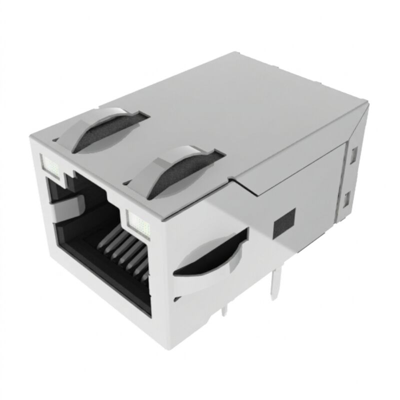
Product Details
Place of Origin: China
Brand Name: LINK-PP
Certification: UL,RoHS,Reach,ISO
Model Number: JXF0-5011NL
Payment & Shipping Terms
Minimum Order Quantity: 50pcs
Price: $ 1.3
Packaging Details: Reel
Delivery Time: In Stock Ship Within 3 Days
Payment Terms: L/C,D/A,D/P,T/T,Western Union
Supply Ability: 5KK/Month
Part Number: |
JXF0-5011NL |
Series: |
PULSEJACK JX0 |
Product Type: |
1×1 RJ45 Integrated Connector Module (ICM) |
Data Rate: |
5GBASE-T |
Transformer Ratio: |
1:1 |
Isolation Voltage: |
2250 VDC |
Operating Temperature: |
-40°C To +85°C |
Height Above PCB: |
13.50mm |
Contact Finish: |
30µin Gold |
Compliance: |
RoHS |
Part Number: |
JXF0-5011NL |
Series: |
PULSEJACK JX0 |
Product Type: |
1×1 RJ45 Integrated Connector Module (ICM) |
Data Rate: |
5GBASE-T |
Transformer Ratio: |
1:1 |
Isolation Voltage: |
2250 VDC |
Operating Temperature: |
-40°C To +85°C |
Height Above PCB: |
13.50mm |
Contact Finish: |
30µin Gold |
Compliance: |
RoHS |
The JXF0-5011NL is an industrial-grade, single-port Gigabit PulseJack Integrated Connector Module (ICM) designed for rugged, high-bandwidth Ethernet applications operating up to 5GBase-T (5 Gbps). Built strictly to IEEE 802.3 standards, the JXF0-5011NL integrates high-performance magnetics, isolation transformers, and a 2-wire (2W) signal line common mode choke into a compact form factor.
Featuring dual Green-Yellow / Green-Yellow bi-colour LEDs, this non-PoE connector provides real-time multi-state link/activity visual feedback without requiring external light pipes. Built with high-temperature UL 94V-0 thermoplastic and 3.20mm tin-plated tails, the JXF0-5011NL is fully qualified for Through-Hole Reflow (THR / Pin-in-Paste) production lines, achieving an MSL 1 unlimited floor life rating and exceptional shock/vibration tolerance across a -40°C to +85°C operating span.
| Parameter | Specification | Standard / Conditions |
| Operating Temperature | -40°C to +85°C | Full bandwidth operation |
| Storage Temperature | -40°C to +85°C | Unmounted / In original tray |
| Dielectric Isolation (Pri:Sec) | 2250 VDC / 60 seconds | Complete primary-to-secondary barrier |
| Moisture Sensitivity Level | MSL 1 (Unlimited) | IPC / JEDEC J-STD-020 |
| Flammability | UL 94V-0 | High-temperature thermoplastic |
| Safety Standard | UL 62368-1 (File No. E216117) | Audio/Video, Information Tech Equipment |
| Cavity Standard | FCC Part 68, Subpart F | Universal RJ45 Modular Plug interface |
| Metric | Frequency Band | Value (Limit) |
| Data Rate | Baseband Ethernet | 5GBase-T (IEEE 802.3) |
| Inductance (OCL Min) | 100 kHz, 0.1 mA | 180 µH Min (Datasheet lists as 180mH) |
| Insertion Loss (Max) | 1.0 MHz – 125 / 250 MHz | -1.0 dB / -1.5 dB |
| Return Loss (Min) |
1 MHz – 40 MHz 40 MHz – 100 MHz 100 MHz – 250 MHz |
-24 dB -19 dB -14 dB (Interpolated formula: -20+[12.5×log10(f/40MHz)]) |
| Crosstalk (Typ) |
10 MHz – 125 MHz 125 MHz – 250 MHz |
-30 dB -20 dB |
| Common Mode Rejection (Min) |
10 MHz – 125 MHz 125 MHz – 250/400 MHz |
-35 dB -30 dB / -25 dB |
| EMI Choke Configuration | Signal Line | 2-Wire (2W), Cable/Signal Line Side |
| Component | Material | Plating / Specifications |
| Contact Interface | Phosphor Bronze | 30 µ-inch Gold over 30 µ-inch min Nickel underplate |
| Solder Tails | Phosphor Bronze | 100 µ-inch min 100% Matte Tin (Lead-free) |
| Shield Shell | Copper Alloy | Nickel plated with Top & Sides EMI grounding tabs |
| Pin Tail Length | 3.20 mm | Optimized for 1.6mm – 2.4mm PCB thickness |
| Packaging | Industrial Tray | 50 pieces per full tray |
| Parameter | Green LED | Yellow LED | Conditions |
| Dominant Wavelength | 568 nm | 585 nm | Typical |
| Luminous Intensity | 8 to 12 mcd | 8 to 12 mcd | @ IF = 20 mA (Typ) |
| Viewing Angle | 100° | 100° | Semi-angle |
| Max Power Dissipation (Pd) | 100 mW MAX | 100 mW MAX | — |
| Max DC Forward Current | 150 mA MAX | 150 mA MAX | Continuous |
| Max Reverse Voltage (Vr) | 5.0 V MAX | 5.0 V MAX | — |
JXF0-5011NL uses a right-angle through-hole construction with a compact footprint.
Important mechanical values include:
| Mechanical Parameter | Specification |
|---|---|
| Connector Width | 16.80mm |
| Overall Length | 25.53mm |
| Height Above PCB | 13.50mm |
| Signal Pin Size | 0.45 × 0.35mm |
| LED Pin Size | 0.50 × 0.50mm |
| Recommended PCB Layout Width | 16.80mm |
| Recommended PCB Layout | See manufacturer drawing |
| Recommended Solder Process | THR / Pin-in-Paste |
JXF0-5011NL is RoHS compliant.
The manufacturer specification identifies:
A: Yes. The JXF0-5012NL PCB footprint includes 14 data/LED holes plus 4 extra PoE holes (Pins 15–18). Because the JXF0-5011NL simply lacks these 4 PoE pins, it can physically plug into a 5012NL footprint without modifications, provided the unused PoE circuits on the board remain unpowered.
A: In a non-PoE design, there is no high continuous DC current passing through the center tap. A 2-wire signal choke on the cable/signal line provides superior differential-mode signal transparency and symmetrical common-mode attenuation without the extra capacitive parasitics introduced by a third tap wire.
A: Yes. Unlike PoE-enabled modules where PoE power paths bypass signal transformers, the JXF0-5011NL provides an uninterrupted 2250 VDC dielectric isolation barrier between the entire primary (cable side) and secondary (PHY side), fully compliant with IEEE 802.3 and UL 62368-1 safety isolation requirements.
A: The internal LEDs are anti-parallel bi-colour diodes. To illuminate Green (568nm), apply forward polarity (+ on Pin 11, - on Pin 12). To illuminate Yellow (585nm), simply reverse the polarity (+ on Pin 12, - on Pin 11).
Tags: