


logo
Send Message
LINK-PP INT'L TECHNOLOGY CO., LIMITED
Products
Product Details
Home > Products > Magnetic RJ45 Jack > JXF0-1011NL Through-hole Reflow RJ45 Gigabit MagJack With 2250VDC Isolation

JXF0-1011NL Through-hole Reflow RJ45 Gigabit MagJack With 2250VDC Isolation

Product Details

Place of Origin: China

Brand Name: LINK-PP

Certification: UL,ROHS,Reach,ISO

Model Number: JXF0-1011NL

Payment & Shipping Terms

Minimum Order Quantity: 10 pcs

Price: Supportive

Packaging Details: Tape & Reel

Delivery Time: in Stock Ship within 3 days

Payment Terms: TT,NET30/60/90 Days

Supply Ability: 4600K.PCS/Month

Get Best Price
Highlight:

JXF0-1011NL

,

1000Base-T RJ45 with LEDs

,

Through-hole Reflow RJ45

Part Number:
JXF0-1011NL
Port Configuration:
1X1
Data Rate:
1Gbps
Integrated Magnetics:
Yes
Transformer Ratio:
1:1
LED Option:
Green-Yellow / Green-Yellow
EMI Choke:
2W, Signal Line
EMI Fingers:
Top & Sides
Shielding:
Shielded
Operating Temperature:
-40°C To +85°C
Part Number:
JXF0-1011NL
Port Configuration:
1X1
Data Rate:
1Gbps
Integrated Magnetics:
Yes
Transformer Ratio:
1:1
LED Option:
Green-Yellow / Green-Yellow
EMI Choke:
2W, Signal Line
EMI Fingers:
Top & Sides
Shielding:
Shielded
Operating Temperature:
-40°C To +85°C
JXF0-1011NL Through-hole Reflow RJ45 Gigabit MagJack With 2250VDC Isolation


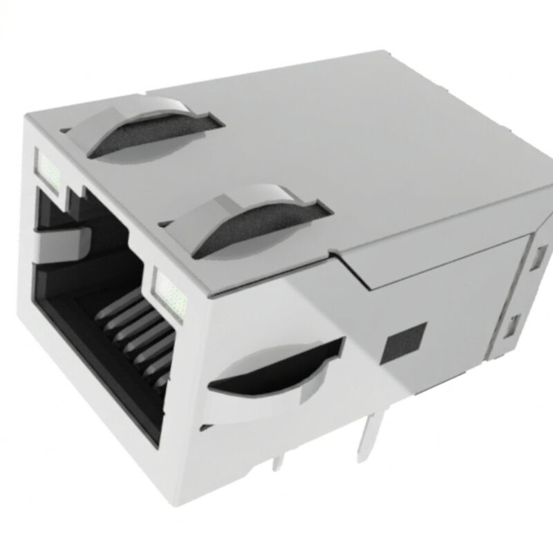
The JXF0-1011NL is an industrial-grade, single-port (1x1) 1000Base-T Gigabit Integrated Connector Module (ICM / PulseJack™). It features integrated magnetics, a 2-wire (2W) signal line common mode choke, and dual Green-Yellow / Green-Yellow bi-colour LEDs in a Non-PoE, 14-pin configuration. Operating across an industrial temperature range of -40°C to +85°C, it delivers 2250 VDC galvanic isolation (Pri:Sec), MSL 1 shelf life, and full compatibility with Through-Hole Reflow (THR / Pin-in-Paste) automated soldering.


JXF0-1011NL THR RJ45 Magjack Overview


The JXF0-1011NL is a robust single-port Gigabit RJ45 Integrated Connector Module (ICM) designed for embedded industrial computing, programmable logic controllers (PLCs), factory robotics, and precision instrumentation. Meeting full IEEE 802.3 specifications, it integrates 1:1 isolation transformers, common mode termination, and a 2-wire (2W) signal line common mode choke into an FCC-compliant footprint.

Equipped with dual Green/Yellow bi-colour LEDs, the JXF0-1011NL provides real-time link, speed, and activity diagnostics without external light pipes. Constructed from high-temperature UL 94V-0 thermoplastic, the connector is specifically engineered for Through-Hole Reflow (THR / Pin-in-Paste) SMT assembly lines. With an MSL 1 rating and J-STD-075 R7 (260°C peak reflow) certification, it eliminates secondary wave soldering, reducing assembly defects and cycle times.


Key Architectural Highlights:


  • True Primary-to-Secondary 2250VDC Isolation: Because this is a pure data (Non-PoE) architecture, complete dielectric isolation is maintained across the entire magnetics assembly, safeguarding PHY transceivers from field surges.
  • Dual Bi-Colour Diagnostic LEDs: Left and right bi-directional LEDs (568nm green / 585nm yellow) allow multi-state status indications driven by dedicated Pins 11–14.
  • Low High-Frequency Attenuation: Superior insertion loss (-1.5 dB max up to 125MHz) and return loss (-16 dB min @ 1–40MHz) guarantee clean eye diagrams and low packet error rates.
  • SMT-Ready THR Construction: 3.20 mm matte-tin solder tails allow automated paste-in-hole reflow soldering, conforming to IPC-A-610 Class 3 barrel-fill requirements.


Technical Specifications of JXF0-1011NL ICM


1. High-Frequency RF Performance (@ 25°C, Operating -40°C to +85°C)


Metric Frequency Range Technical Limit Standard / Conditions
Data Rate Baseband Ethernet 1000Base-T (1 Gbps) IEEE 802.3 Compliant
Open Circuit Inductance (OCL) 100 kHz, 0.1 mA 350 µH Min (Datasheet lists 350mH) Media Side
Turns Ratio All 4 Channels 1:1 Differential Pairs
Insertion Loss (Max) 1.0 MHz – 125 MHz -1.5 dB Media Side to PHY
Return Loss (Min)

1 MHz – 40 MHz

40 MHz – 100 MHz

-16 dB

-9 dB

100Ω System Impedance
Crosstalk (Typ) 10 MHz – 125 MHz -24 dB Inter-channel suppression
Common Mode Rejection (Min) 10 MHz – 125 MHz -24 dB Common-mode noise filter
Dielectric Isolation 60 Seconds 2250 VDC Complete Pri:Sec Barrier
EMI Choke Topology Signal Line 2-Wire (2W) Cable-Side Choke


2. Environmental, Material & Mechanical Ratings


Parameter Specification Benchmark / Reference Standard
Operating / Storage Temperature -40°C to +85°C Full industrial grade
Housing Construction High-temp Engineering Thermoplastic UL 94V-0 Flammability certified
Contact Interface Material Phosphor Bronze 30 µ-inch Gold over 30 µ-inch min Nickel
Solder Tail Plating Phosphor Bronze 100 µ-inch min Matte Tin (Lead-free)
Shield Shell Copper Alloy Nickel Plated with Top & Side EMI Fingers
Moisture Sensitivity Level (MSL) MSL 1 (Unlimited) IPC / JEDEC J-STD-020
Solder Heat Resistance Peak 260°C Reflow / Wave IPC / JEDEC J-STD-075 (R7 Classification)
Safety Certification File No. E216117 UL 62368-1 Certified
Standard Packaging Industrial Plastic Tray 50 pieces / full tray


3. Integrated Bi-Colour LED Specifications


Metric Green LED Yellow LED Test Conditions
Dominant Wavelength 568 nm 585 nm Typical
Luminous Intensity 8 to 12 mcd 8 to 12 mcd @ IF = 20 mA (Typ)
Viewing Angle 100° 100° Wide angle visibility
Max Power Dissipation (Pd) 100 mW MAX 100 mW MAX
Max Continuous Forward Current 150 mA MAX 150 mA MAX Continuous DC
Max Reverse Voltage (Vr) 5.0 V MAX 5.0 V MAX


JXF0-1011NL 1000Base-T RJ45 with LEDs Datasheet:


1. JXF0-1011NL RJ45 Datasheet - Schematic


JXF0-1011NL RJ45 Datasheet - Schematic


2. JXF0-1011NL RJ45 Connector Mechanicals 


JXF0-1011NL RJ45 Connector Mechanicals


Mechanical Dimensions & Pinout Guide: 


PCB RECOMMENDED PINOUT (Component Side View - 14 Pins)
   [12] [11] (Left Bi-Colour LED)             [14] [13] (Right Bi-Colour LED)
       [10] [8]  [6]  [4]  [2]   <- Signal Row 2
         [9]  [7]  [5]  [3]  [1]   <- Signal Row 1
 (Shield Post)                                          (Shield Post)


  • Physical Outline: 16.80 mm (Width) × 25.53 mm (Length) × 13.50 mm (Height above PCB).
  • Suggested Panel Cutout: 17.82 mm × 14.01 mm. Latch orientation: Latch-Up.
  • Pin Assignments (14 Electrical Pins + 2 Shield Tabs):
    • Pin 1: CT 1 (Center Tap for channel 1)
    • Pins 2 & 3: TRD1+ / TRD1-
    • Pins 4 & 5: TRD2+ / TRD2-
    • Pins 6 & 7: TRD3+ / TRD3-
    • Pins 8 & 9: TRD4+ / TRD4-
    • Pin 10: Bob Smith chassis termination (isolated via 1000pF / 2kV capacitor and 4× 75Ω resistors)
    • Pins 11 & 12: Drive Left Bi-colour LED (Anti-parallel: Pin 11+/12- = Green; Pin 12+/11- = Yellow)
    • Pins 13 & 14: Drive Right Bi-colour LED (Anti-parallel: Pin 13+/14- = Green; Pin 14+/13- = Yellow)
  • Drill Hole Specifications:
    • 10× Signal Holes: Finished diameter Ø0.89 mm (Pad diameter: Ø1.40 mm recommended).
    • 4× LED Holes: Finished diameter Ø1.02 mm.
    • 2× Plastic Standoff Pegs: Ø1.57 mm.
    • 2× Shield Grounding Posts: Ø3.25 mm.


THR / Pin-in-Paste Processing:


JXF0-1011NL belongs to the JX0 Pin-in-Paste / Through-Hole Reflow platform.


Supported assembly processes include: Pin-in-Paste / THR and wave soldering.


The manufacturer specifies J-STD-020 Level 1 and J-STD-075 R7, including a 260°C maximum through-wave-solder condition.


Frequently Asked Questions: 

Q1: How do I wire a microcontroller GPIO to drive the bi-colour LEDs on Pins 11–14?

A: The internal LEDs are wired anti-parallel. Connect Pin 11 and Pin 12 to two separate push-pull GPIOs with a current-limiting resistor (e.g., 150Ω–330Ω for 3.3V VCC). Setting GPIO_A HIGH and GPIO_B LOW lights Green (568nm); setting GPIO_A LOW and GPIO_B HIGH lights Yellow (585nm). Setting both LOW or HIGH turns the LED OFF.


Q2: Can JXF0-1011NL be installed on a PCB footprint designed for JXF0-1012NL?

A: Yes. The JXF0-1012NL footprint has 18 holes (10 signal + 4 LED + 4 PoE). The JXF0-1011NL aligns with the 10 signal and 4 LED holes, leaving the 4 PoE holes (Pins 15–18) completely unpopulated.


Q3: Why does JXF0-1011NL feature a 2-wire choke instead of a 3-wire choke?

A: Since there is no PoE DC bias current in the JXF0-1011NL, a 2-wire signal line choke on the cable side provides symmetrical common-mode attenuation without the stray capacitance or insertion loss associated with a third PoE center-tap tap winding.