



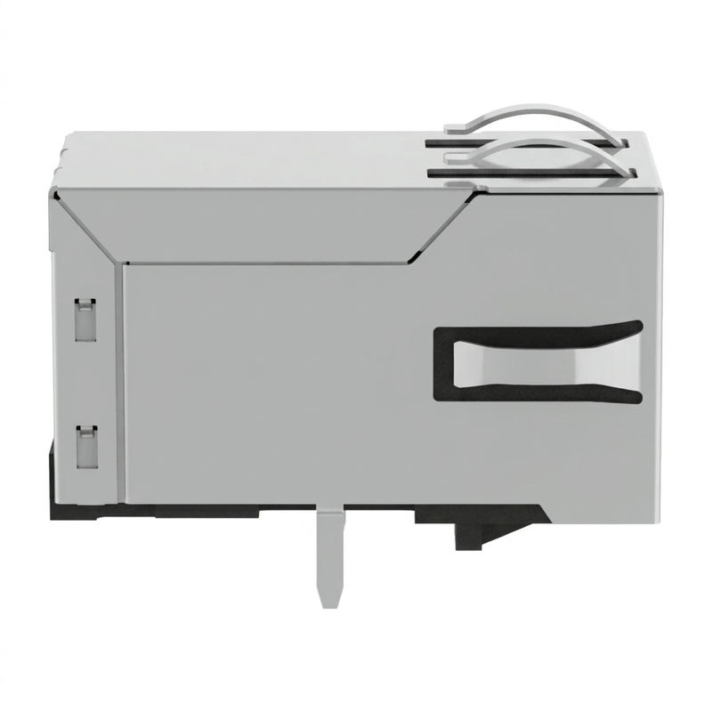
Product Details
Place of Origin: China
Brand Name: LINK-PP
Certification: UL,ROHS,Reach,ISO
Model Number: JXF0-1010NL
Payment & Shipping Terms
Minimum Order Quantity: 50/500/1000/25K
Price: $0.45-$0.7
Packaging Details: 50pcs/tray,1200pcs/carton
Delivery Time: 1-2 Weeks
Payment Terms: TT,NET30/60/90 Days
Supply Ability: 4500K-PCS/Month
Data Rate: |
1000Base-T (1 Gbps) |
Latch: |
Up |
Open Circuit Inductance (OCL): |
350 µH Min |
Turns Ratio: |
1:1 |
Dielectric Isolation: |
2250 VDC |
EMI Choke: |
2-Wire (2W) |
Part Number: |
JXF0-1010NL |
Soldering Type: |
Through-Hole Reflow (THR / Pin-in-Paste) |
Data Rate: |
1000Base-T (1 Gbps) |
Latch: |
Up |
Open Circuit Inductance (OCL): |
350 µH Min |
Turns Ratio: |
1:1 |
Dielectric Isolation: |
2250 VDC |
EMI Choke: |
2-Wire (2W) |
Part Number: |
JXF0-1010NL |
Soldering Type: |
Through-Hole Reflow (THR / Pin-in-Paste) |
The JXF0-1010NL is a 1×1 1000Base-T RJ45 integrated magnetic connector from the PulseJack JX0 series. It combines the 8P8C Ethernet interface with integrated 1:1 isolation transformers and 2W signal-line common-mode chokes in a shielded, right-angle, tab-up package. The model has no LEDs and no supported PoE, making it suitable for Gigabit Ethernet equipment that requires a simplified, data-only RJ45 interface. The JX0 series is designed for −40°C to +85°C industrial temperature operation and supports through-hole reflow (THR) processing.
The JXF0-1010NL is a ruggedized single-port Gigabit RJ45 connector integrating internal isolation transformers, impedance termination, and a 2-wire (2W) signal-line common mode choke into an FCC Part 68 compliant form factor. Meeting all IEEE 802.3ab specifications, this connector provides uncompromised 1 Gbps transmission for programmable logic controllers (PLCs), factory robotics, industrial PCs, and optical test instrumentation.
By eliminating integrated LEDs and PoE pins, the JXF0-1010NL provides an ultra-clean 10-pin PCB footprint. This architecture reduces parasitic capacitance, eliminates optical cross-talk for enclosures utilizing front-panel light pipes, and leaves inner PCB layers open for continuous ground planes and optimized 100Ω differential routing. Built from high-temperature UL 94V-0 thermoplastic with 3.20 mm matte-tin solder tails, the connector is specifically designed for Through-Hole Reflow (THR / Pin-in-Paste) automated soldering lines, eliminating secondary wave soldering stages while meeting IPC/JEDEC J-STD-075 (Category R7, 260°C peak) standards.
JXF0-1010NL is specified for 1000Base-T Gigabit Ethernet and incorporates four 1:1 transformer channels for the four differential Ethernet pairs. The internal schematic shows four symmetric transformer paths between the PCB side and cable side.
The JXF0-1010NL contains no integrated LEDs. This is useful where Link/Activity indication is handled through an external light pipe, front-panel indicator, software interface or is not required.
The no-LED configuration also reduces the number of connector pins compared with the corresponding LED version JXF0-1011NL.
The manufacturer data table specifies Supported PoE: No for JXF0-1010NL. Unlike the JXF0-1012NL 90W PoE version, this model is intended for Ethernet data connectivity without a PoE power path.
JXF0-1010NL is specified with 2250 VDC / 60 sec transformer isolation. The isolation rating applies across the transformer isolation barrier as stated in the manufacturer datasheet.
The specified operating temperature range is −40°C to +85°C, supporting Ethernet equipment deployed in industrial and extended-temperature environments.
The integrated shield incorporates top and side EMI fingers, providing a defined metal-shield interface to the equipment enclosure. The manufacturer identifies the shield as nickel-plated copper alloy.
The JX0 series is designed for Through-Hole Reflow (THR) processing. The manufacturer also specifies J-STD-002 solderability testing and J-STD-075 R7 classification with a 260°C maximum through-wave-solder specification.
| Parameter | Specification |
|---|---|
| Series | PULSEJACK JX0 |
| Part Number | JXF0-1010NL |
| Connector Type | 1×1 RJ45 / 8P8C |
| Ethernet Speed | 1000Base-T |
| Integrated Magnetics | Yes |
| Turns Ratio | 1:1 |
| LED | None |
| PoE | No |
| EMI Choke | 2W, Signal Line |
| EMI Shield | Top & Sides EMI Fingers |
| Isolation | 2250 VDC / 60 sec |
| Mounting | Through Hole |
| Orientation | Right Angle / Side Entry |
| Tab Direction | Up |
| THR | Compatible |
| Operating Temperature | −40°C to +85°C |
| Housing | Thermoplastic, UL 94V-0 or better |
| Contact Material | Phosphor Bronze |
| Contact Plating | 30 µin Gold |
| Shield Material | Copper Alloy, Nickel Plated |
| Packaging | Tray, 50 pcs |
| Part Status | Active |
| Parameter | JXF0-1010NL Specification |
|---|---|
| Ethernet Data Rate | 1000Base-T |
| Turns Ratio | 1:1 |
| Inductance, Media Side | 350 µH minimum* |
| Insertion Loss | −1.5 dB max. |
| Return Loss, 1–40 MHz | −16 dB min. |
| Return Loss, 40–100 MHz | −9 dB min. |
| Cross Talk, 10–125 MHz | −24 dB typ. |
| Common Mode Rejection, 10–125 MHz | −24 dB min. |
| Transformer Isolation | 2250 VDC / 60 sec |
| Operating Temperature | −40°C to +85°C |
▶ The internal schematic consists of four 1:1 transformer channels. Each Ethernet pair passes through the integrated transformer and a 2W common-mode choke located on the signal/cable path.
▶The no-LED version also integrates a termination network consisting of 4 × 75 Ω resistors and a 1000 pF / 2 kV capacitor, as shown in the manufacturer schematic.
▶ This means the engineer does not need to reproduce the complete transformer and common-mode choke structure as separate magnetic components on the PCB.
The JXF0-1010NL uses a compact 10-signal-pin configuration without the additional LED or PoE pins found on other variants.
| Pin | Function |
|---|---|
| 1 | CT1 |
| 2 | TRD1+ |
| 3 | TRD1− |
| 4 | TRD2+ |
| 5 | TRD2− |
| 6 | TRD3+ |
| 7 | TRD3− |
| 8 | TRD4+ |
| 9 | TRD4− |
| 10 | GND / integrated termination reference |
The internal schematic confirms the four differential transformer channels and the pin-10 termination connection.
PCB SIDE

  10    8    6    4    2
   9    7    5    3    1

10  → GND
 9  → TRD4-
 8  → TRD4+
 7  → TRD3-
 6  → TRD3+
 5  → TRD2-
 4  → TRD2+
 3  → TRD1-
 2  → TRD1+
 1  → CT1
Always verify pin numbering against the controlled mechanical drawing before PCB release.
A: Yes. The physical outline, guide pegs, and the 10 signal pins (Pins 1–10) are dimensionally identical across the entire JXF0 family. If your board features an 18-hole master footprint, JXF0-1010NL will solder into place perfectly, leaving the LED (Pins 11–14) and PoE (Pins 15–18) holes empty.
A: Beyond lower component cost, JXF0-1010NL is selected when:
A: Yes. Compliant with IPC/JEDEC J-STD-020 MSL 1 and J-STD-075 Category R7, the high-temperature housing withstands full reflow soldering profiles with peak temperatures up to 260°C.
Tags: