



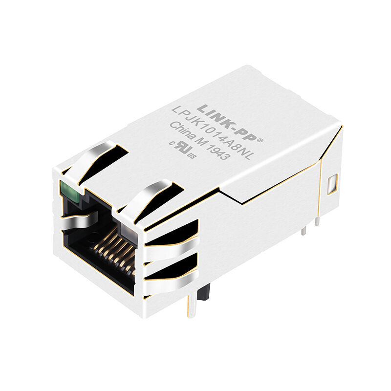
Product Details
Place of Origin: GuangDong, China
Brand Name: LINK-PP
Certification: UL,ROHS,Reach,ISO
Model Number: LPJK1014A8NL
Document: LPJK1014A8NL.pdf
Payment & Shipping Terms
Minimum Order Quantity: 50/500/1000
Price: $0.09-$1.05
Packaging Details: 50 pcs in 1 tray, 24tray in 1 carton, which is 32*30*31,8.5 KGS (1200pcs) of each carton
Delivery Time: In Stock Ship Within 3 Days
Payment Terms: TT,NET30/60/90 Days
Supply Ability: 3000000/Month
Compatible Brands: |
Belfuse |
Number Of Ports: |
1X1 |
Latch: |
Up |
Data Rate: |
100Base-T |
PoE: |
PoE |
LED Option: |
With |
EMl Tabs: |
With |
Mounting Type: |
THT |
Solder Type: |
Wave |
Operating Temperature Range: |
0°C To +70°C |
Compatible Brands: |
Belfuse |
Number Of Ports: |
1X1 |
Latch: |
Up |
Data Rate: |
100Base-T |
PoE: |
PoE |
LED Option: |
With |
EMl Tabs: |
With |
Mounting Type: |
THT |
Solder Type: |
Wave |
Operating Temperature Range: |
0°C To +70°C |
The 0826-1L1T-57-F is a single-port (1x1) 10/100Base-T Fast Ethernet MagJack featuring integrated IEEE 802.3at PoE+ (30W) power delivery capability. Key specifications include a Tab Up (latch up) port orientation, Through-Hole PCB mounting, 1500 Vrms dielectric isolation, an operating temperature of 0°C to +70°C, and integrated Green (Left) / Green-Yellow (Right) LEDs. It incorporates internal magnetics that prevent core saturation under up to 600mA continuous DC current, standardizing power and data connectivity in IP cameras, VoIP hardware, and access control panels.
The 0826-1L1T-57-F is an industry-standard, single-port (1x1) MagJack Integrated Connector Module (ICM) engineered for commercial Ethernet devices requiring high-reliability data transmission and up to 30W of Power over Ethernet (PoE+). Fully compliant with IEEE 802.3 10/100Base-T and IEEE 802.3at Type 2 standards, this connector integrates transmission transformers, common mode chokes, Bob Smith impedance termination, and high-current PoE+ power feed circuits within a standard-height RJ45 housing.
Engineered with a Tab Up (TU) port orientation, the 0826-1L1T-57-F features integrated Green / Green-Yellow (G/GY) diagnostic LEDs to provide immediate port status and link/activity visibility without requiring dedicated light pipes. Its robust copper-alloy outer shield is equipped with Top & Side EMI tabs to guarantee continuous grounding contact to the chassis panel, ensuring compliance with FCC Part 15 Class B emissions. Operating across a 0°C to +70°C temperature range, it is the optimal component for IP security cameras, access control terminals, VoIP phones, and smart IoT gateways.
| Parameter | Specification | Standard / Reference |
| Product Series | MagJack® ICMs | Bel Fuse Magnetic Solutions |
| Data Rate | 10/100Base-T (Fast Ethernet) | IEEE 802.3 Compliant |
| PoE Rating | PoE+ 30 W (Up to 600mA DC continuous) | IEEE 802.3at Type 2 |
| Operating Temperature | 0°C to +70°C | Commercial Operating Range |
| Storage Temperature | -40°C to +85°C | In packaging / Unmounted |
| Dielectric Isolation (DWV) | 1500 Vrms Min | 60 seconds (Pri:Sec) |
| Port Configuration | 1x1 Port, Tab Up (Latch-Up) | Standard Profile |
| Mounting Style | Through-Hole Mount | Wave / Hand Soldering |
| EMI Tabs | Yes (Top and Sides) | Chassis spring grounding |
| RoHS Compliance | Yes (RoHS 6/6 Compliant) | Suffix "-F" designation |
| Metric | Frequency Range | Technical Limit | Notes |
| Turns Ratio | TX & RX Channels | 1CT:1CT (TX) / 1CT:1CT (RX) | ±2% Center-Tapped Symmetrical |
| Open Circuit Inductance (OCL) | 100 kHz, 100 mV | 350 µH Min | With 8mA DC Bias applied |
| Insertion Loss (Max) | 1.0 MHz – 100 MHz | -1.0 dB Max | Flat high-frequency transmission |
| Return Loss (Min) |
1.0 MHz – 30 MHz 30 MHz – 60 MHz 60 MHz – 80 MHz |
-18 dB Min -14 dB Min -12 dB Min |
100Ω System Impedance |
| Common Mode Rejection (Min) | 1.0 MHz – 100 MHz | -30 dB Min | EMI common-mode attenuation |
| Crosstalk (Min) | 1.0 MHz – 100 MHz | -35 dB Min | Channel-to-channel isolation |
Inside the 0826-1L1T-57-F, differential pairs for 10/100Base-TX (Pins 1/2 for TX, Pins 3/6 for RX) route through 1:1 isolation transformers and common mode chokes. The center taps of the cable-side transformers connect directly to dedicated PoE+ power rails:
A: While rated for 0°C to +70°C, outdoor installations must account for solar loading and internal heat dissipation from the 30W PoE circuit. If internal enclosure temperatures risk exceeding +70°C, hardware engineers should upgrade to the industrial-grade sibling 0826-1X1T-57-F (-40°C to +85°C).
A: The left LED is a single-colour Green diode (typically 2.1V–2.2V forward drop at 20mA). The right LED is a dual-colour Green/Yellow diode wired in anti-parallel or common-cathode depending on the sub-revision; drive current should be limited to 10mA–20mA via series resistors from the PHY or SoC GPIOs.
A: Conventional magnetics saturate when high DC currents pass through differential windings. The 0826-1L1T-57-F uses high-current center taps with high-saturation ferrite cores tested to maintain ≥350 µH OCL even with an 8mA DC bias superimposed over continuous PoE currents, ensuring zero link drops.