



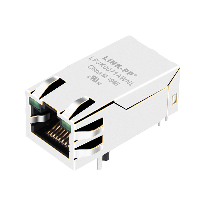
Product Details
Place of Origin: China
Brand Name: LINK-PP
Certification: UL,ROHS,Reach,ISO
Model Number: LPJK0071AWNL
Document: LPJK0071AWNL.pdf
Payment & Shipping Terms
Minimum Order Quantity: 50/500/1000/25K
Price: $ 1.06
Packaging Details: 50pcs/tray,1200pcs/carton
Delivery Time: About 3 Days
Payment Terms: TT,NET30/60/90 Days,Western Union
Supply Ability: 4200K-PCS/Month
Part Number: |
LPJK0071AWNL |
Type: |
Gigabit RJ45 MagJack |
Compatible Brands: |
Belfuse |
Number Of Ports: |
1X1 |
Latch: |
Up |
Data Rate: |
1000Base-T |
PoE: |
Non |
LED Option: |
With |
EMl Tabs: |
With |
Mounting Type: |
THT |
Solder Type: |
Wave |
Operating Temperature Range: |
0°C To +70°C |
Part Number: |
LPJK0071AWNL |
Type: |
Gigabit RJ45 MagJack |
Compatible Brands: |
Belfuse |
Number Of Ports: |
1X1 |
Latch: |
Up |
Data Rate: |
1000Base-T |
PoE: |
Non |
LED Option: |
With |
EMl Tabs: |
With |
Mounting Type: |
THT |
Solder Type: |
Wave |
Operating Temperature Range: |
0°C To +70°C |
The 0826-1G1T-23-F is a premier single-port (1x1) Gigabit Integrated Connector Module (ICM) engineered for high-bandwidth networking devices. Featuring an advanced 12-core magnetic topology with integrated common-mode filtering across all four differential pairs, this Tab-Up, Non-PoE connector delivers ultra-low insertion loss up to 125 MHz, superior EMI suppression, and 50 micro-inch gold plating for demanding commercial Ethernet hardware.
| Parameter | Specification |
|---|---|
| Speed | 1000BASE-T (Gigabit Ethernet) |
| Magnetic Topology | 12-Core Design |
| Port Configuration | 1×1 Single Port |
| Latch Orientation | Tab-Up |
| Operating Temperature | 0°C to +70°C |
| PoE Capability | Non-PoE |
| Contact Interface | 50 μin Hard Gold |
| Optical Status | Dual Green LEDs |
| Isolation HiPot | 1500 Vrms |
| Solder Rating | 260°C Max. (10s) |
| Safety Approvals | UL E196366 / E169987 |
| Shield | Copper Alloy with EMI Ta |
| Category | Engineering Parameter | Technical Benchmark | Test Condition / Notes |
|---|---|---|---|
| Basic Identification | Part Number (P/N) | 0826-1G1T-23-F | Rev. F Active Lifecycle |
| Series Name | Gigabit MagJack | Integrated Connector Module | |
| Ethernet & Magnetics | Transmission Rate | 1000BASE-T (Gigabit Ethernet) | Backward compatible 10/100Base-T |
| Core Architecture | 12 Cores (4 Differential Channels) | TP1, TP2, TP3, TP4 individual filtering | |
| Turns Ratio (All Channels) | 1CT : 1CT (±2%) | Matched Transmit & Receive channels | |
| Open Circuit Inductance (OCL) | 350 μH MIN. | @ 100 kHz, 100 mVrms, 8 mA DC Bias | |
| Insertion Loss | 0.1–1.0 MHz: -1.1 dB MAX. 1.0–65 MHz: -0.5 dB MAX. 65–100 MHz: -0.8 dB MAX. 100–125 MHz: -1.2 dB MAX. |
Evaluated up to 125 MHz for extended Gigabit headroom | |
| Return Loss (100 Ω Ref.) | 0.5–40 MHz: -18 dB MIN. 40–100 MHz: -(12 + 20 log(f/80 MHz)) dB MIN. |
Optimal return loss ensures low packet jitter | |
| Common Mode to CM Rejection | -30 dB MIN. | 100 kHz–100 MHz | |
| Common Mode to DM Rejection | -35 dB MIN. | 100 kHz–100 MHz | |
| Dielectric Isolation (HiPot) | 1500 Vrms MIN. | 100% production checked per IEEE 802.3 | |
| PoE Power Rating | Non-PoE | Pure data lines; isolated termination | |
| Optical (LED Matrix) | LED 1 (Right Front) | Pure Green | Pin 14 (+) Anode / Pin 13 (-) Cathode |
| LED 2 (Left Front) | Pure Green | Pin 16 (+) Anode / Pin 15 (-) Cathode | |
| LED Optical Characteristics | VF = 2.2 V TYP. λD = 570 nm TYP. |
@ IF = 20 mA test condition | |
| Mechanical & Materials | Mounting Type | THT (Through Hole Mount) | Right angle / Horizontal PCB exit |
| Latch / Tab Direction | Tab-Up (Latch Up) | Top latch engagement | |
| Housing Material | Thermoplastic PA, Black | Flammability rating UL 94V-0 | |
| Contact Interface Plating | 50 micro-inches hard gold | Over 30 micro-inches nickel underplate | |
| Shielding Shell | Nickel-plated copper alloy | With continuous top/side EMI spring tabs | |
| Solder Pins & Leads | Tin-coated copper wire, dia. 0.018" | Ground leads 100% pre-solder dipped | |
| Overall Dimensions | 32.77 mm (L) × 16.31 mm (W) × 13.61 mm (H) | 1.290" (D) × 0.642" (W) × 0.536" (H) | |
| Panel Cutout Recommendation | 17.07 mm [0.672"] Wide × 14.00 mm [0.551"] High | Distance to front surface: 2.03 mm [0.080"] | |
| Thermal & Reliability | Operating Temperature | 0°C to +70°C | Commercial temperature profile |
| Wave Soldering Limit | 260°C MAX. for 10 Seconds MAX. | Compatible with lead-free wave soldering | |
| Regulatory Compliance | Regulatory Compliance | RoHS Compliant, FCC Cavity Compliant | cURus File #E196366 & #E169987 |
| Standard Packaging | 40 pcs / tray; 10 trays (400 pcs) / master box | Tray P/N: 0200-9999-F6 (Top) / 0200-9999-F7 (Bottom) |
[ PHY CHIP SIDE ]                    [ CABLE / RJ45 SIDE ]
    Channel 1: TRD1+ (Pin 11) ──┐ 1CT : 1CT ┌───[CMC]─── J1 (TRP1+)
               TRCT1 (Pin 12) ──┼───┐   ┌───┤
               TRD1- (Pin 10) ──┘   │   │   └───[CMC]─── J2 (TRP1-)
                                    │   │
    Channel 2: TRD2+ (Pin 4)  ──┐ 1CT : 1CT ┌───[CMC]─── J3 (TRP2+)
               TRCT2 (Pin 6)  ──┼───┐   ┌───┤
               TRD2- (Pin 5)  ──┘   │   │   └───[CMC]─── J6 (TRP2-)
                                    │   │
    Channel 3: TRD3+ (Pin 3)  ──┐ 1CT : 1CT ┌───[CMC]─── J4 (TRP3+)
               TRCT3 (Pin 1)  ──┼───┐   ┌───┤
               TRD3- (Pin 2)  ──┘   │   │   └───[CMC]─── J5 (TRP3-)
                                    │   │
    Channel 4: TRD4+ (Pin 8)  ──┐ 1CT : 1CT ┌───[CMC]─── J7 (TRP4+)
               TRCT4 (Pin 7)  ──┼───┐   ┌───┤
               TRD4- (Pin 9)  ──┘   │   │   └───[CMC]─── J8 (TRP4-)
                                    ▼   ▼
               [ Bob Smith Termination: 4x 75Ω Resistors + 1000pF/2kV to Shield ]
1. Recommended PCB Hole Layout:
2. Recommended Panel Bezel Cutout:
3. Wave Soldering Thermal Envelope:
No. The 0826-1G1T-23-F is a Non-PoE Gigabit connector. It is engineered strictly for high-speed data transmission up to 1000BASE-T. If your system requires PoE or PoE+ power injection, you should select PoE-rated series like Bel Fuse 0826-1X1T or LINK-PP LPJK series.
The 12-core topology incorporates dedicated isolation transformers and common mode filters across all 4 differential pairs (8 conductors) required for Gigabit Ethernet. This design minimizes packet collisions, eliminates inter-pair crosstalk, and ensures high signal integrity up to 125 MHz.
Both LED 1 and LED 2 are standard Green LEDs. LED 1 (right) is driven with positive on Pin 14 and ground on Pin 13. LED 2 (left) is driven with positive on Pin 16 and ground on Pin 15. Both feature a forward voltage drop of approximately 2.2V at 20 mA.