



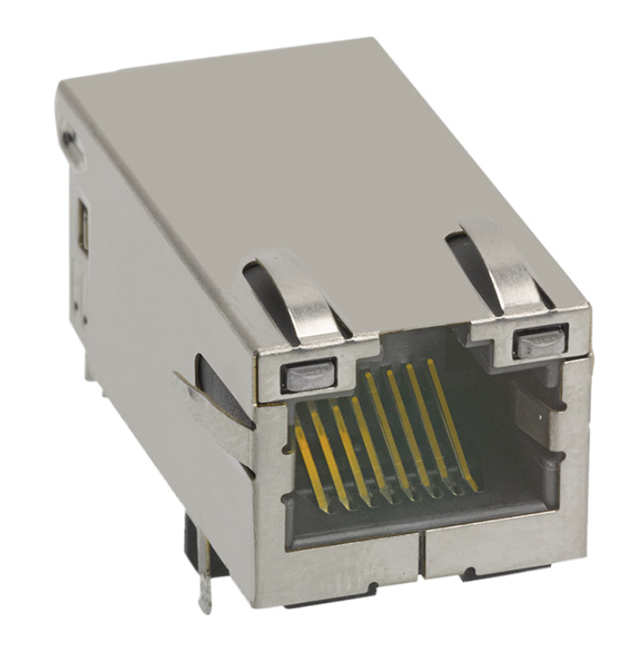
Product Details
Place of Origin: Guangdong,China
Brand Name: LINK-PP
Certification: UL,ROHS,Reach,ISO
Model Number: 0826-1X1T-GH-F
Document: LPJK6064AONL.pdf
Payment & Shipping Terms
Minimum Order Quantity: 50pcs
Price: $1.05
Packaging Details: 50pcs/tray,1200pcs/carton
Delivery Time: in Stock Ship within 3 days
Payment Terms: NET30/60/90 Days,D/A,D/P,T/T
Supply Ability: 250000-320000/Month
Part Number: |
0826-1X1T-GH-F |
Product Type: |
Integrated Connector Module (ICM) |
Ethernet Speed: |
1000BASE-T |
Port Configuration: |
Single Port, 1×1 |
PoE Capability: |
PoE+ 30 W |
RJ45 Tab: |
Tab Up |
Mounting: |
Through Hole Mount |
LED Configuration: |
OG/Y |
Operating Temperature: |
-40°C To +85°C |
EMI Tabs: |
Yes |
OCL: |
350 µH Minimum |
HiPot: |
2250 VDC |
Part Number: |
0826-1X1T-GH-F |
Product Type: |
Integrated Connector Module (ICM) |
Ethernet Speed: |
1000BASE-T |
Port Configuration: |
Single Port, 1×1 |
PoE Capability: |
PoE+ 30 W |
RJ45 Tab: |
Tab Up |
Mounting: |
Through Hole Mount |
LED Configuration: |
OG/Y |
Operating Temperature: |
-40°C To +85°C |
EMI Tabs: |
Yes |
OCL: |
350 µH Minimum |
HiPot: |
2250 VDC |
The 0826-1X1T-GH-F is an industrial-grade, single-port (1x1) Gigabit Ethernet Integrated Connector Module (ICM) designed with integrated magnetics and Power over Ethernet Plus (PoE+) capabilities. Fully compliant with IEEE 802.3at standards, it delivers up to 30W of continuous power (720 mA @ 57 VDC) while maintaining a robust 2250 VDC dielectric isolation.
Configured in a space-efficient Tab-Up, Through-Hole form factor with bi-color status LEDs, it operates reliably across an extended temperature range of -40°C to +85°C, making it the premier choice for industrial IoT gateways, IP security cameras, high-power wireless access points (WAPs), and embedded computing platforms
| Parameter | Value | Engineering Notes / Reference |
| Part Number (MPN) | 0826-1X1T-GH-F | Drawing Revision: Rev. D |
| Port Configuration | 1x1 (Single Port), Tab-Up | Standard Height Profile |
| Ethernet Data Rate | 10/100/1000BASE-T (Gigabit) | 4-Pair Balanced Transformer |
| Mounting Type | Through-Hole Mount (THT) | Wave Soldering: Peak 260°C Max (≤ 10s) |
| Housing Material | Thermoplastic PA, Black | Flammability Rating UL 94V-0 |
| Contact Plating | 50 µ-inch Hard Gold over 30 µ-inch Nickel | Conforms to FCC rules and regulations |
| Shielding | Copper Alloy, Nickel-Plated | Integrated EMI Tabs (Fingers) |
| Operating Temperature | -40°C to +85°C | Extended / Industrial Temperature |
| Agency Certifications | UL Recognized (File #E196366 & E169987) | RoHS Compliant |
| Metric | Specification | Compliance / Test Condition |
| PoE Classification | PoE+ (IEEE 802.3at Compliant) | Up to 30W Power Delivery |
| Continuous Current Rating | 720 mA Max. @ 57 VDC Continuous | Balanced DC Line Current |
| Peak Inrush Current | 1.2 A Max. @ 57 VDC | Duration: 200 ms |
| Dielectric Isolation (Hipot) | 2250 VDC | 100% Production Tested (IEEE 802.3) |
| Turns Ratio (TP1 to TP4) | 1CT : 1CT ±2% | Matched across all 4 channels |
| Open Circuit Inductance (OCL) | 350 µH Min. | 100 kHz, 100 mVrms, 11 mA DC Bias |
| Insertion Loss |
0.1 MHz – 1.0 MHz: -1.1 dB Max 1.0 MHz – 65 MHz: -0.8 dB Max 65 MHz – 100 MHz: -1.0 dB Max 100 MHz – 125 MHz: -1.2 dB Max |
Exceeds Gigabit Signal Integrity Specs |
| Return Loss (Min.) |
0.5 MHz – 40 MHz: -18 dB 40 MHz – 100 MHz: -[12 - 20·log(f/80MHz)] dB |
Matched 100 Ω Differential Lines |
| CM to CM Rejection | -30 dB Min. (100 kHz – 100 MHz) | Common-Mode Filtering |
| CM to DM Rejection | -35 dB Min. (100 kHz – 100 MHz) | Crosstalk & Radiation Suppression |
| Indicator | Color | Forward Voltage Typ. | Dominant Wavelength | Pin Allocation & Polarity |
| LED 1 (Left) | Yellow | 2.1 V | 590 nm | Pin 17 (+) / Pin 18 (-) |
| LED 2 (Right) | Orange | 2.0 V | 610 nm | Pin 19 (+) / Pin 20 (-) |
| LED 2 (Right) | Green | 2.2 V | 570 nm | Pin 19 (-) / Pin 20 (+) (Bi-Color) |
The 0826-1X1T-GH-F uses through-hole PCB mounting with a Tab Up RJ45 configuration and standard height profile. The mechanical drawing provides the complete connector outline, terminal positions, mounting geometry, panel opening recommendation, and lead dimensions.
Important mechanical details shown on the drawing include:
| Mechanical Feature | Drawing Information |
|---|---|
| Mounting | Through Hole |
| Port Orientation | Tab Up |
| Profile | Standard |
| Connector Width Reference | 0.500 in [12.70 mm] |
| Connector Overall Length Reference | 1.290 in [32.77 mm] |
| Front Height Reference | 0.642 in [16.31 mm] |
| PCB-related Height Reference | 0.536 in [13.61 mm] |
| Suggested Panel Opening Width | 0.672 in [17.07 mm] |
| Suggested Panel Opening Height | 0.551 in [14.00 mm] |
| Suggested Panel Opening Depth/Reference | 0.080 in [2.03 mm] |
These dimensions should be treated as drawing references and checked against the latest controlled drawing before production tooling or PCB release.
The 0826-1X1T-GH-F is designed for 1-port Gigabit Ethernet applications requiring integrated magnetics and PoE+ capability.
Typical application areas include:
For Ethernet-powered network devices where the RJ45 interface and magnetics need to be integrated into a single PCB-mounted component.
The -40°C to +85°C operating range supports applications exposed to wider ambient-temperature conditions.
The single-port 1×1 configuration is appropriate for embedded boards and networking systems requiring a compact integrated Ethernet interface.
Useful where 1000BASE-T connectivity, PoE capability, status LEDs, and through-hole assembly are part of the hardware requirements.
Suitable for connected devices requiring a standard Gigabit Ethernet interface with integrated magnetics.
When evaluating secondary sources or mitigating supply chain bottlenecks, compare the following pin-compatible and functional alternatives:
| Manufacturer | Alternative Part Number | Speed | PoE Standard | Drop-in Compatibility Note |
| Bel Fuse | 0826-1X1T-GH-F | 1GbE | PoE+ (30W) | Original Baseline MPN |
| Pulse Electronics | JXK0-0115NL / JK0-0177NL |
1GbE | PoE+ (30W) | Functional match; verify LED forward voltage and footprint center-tap pitch. |
| Wurth Elektronik | 7499111440 | 1GbE | PoE+ (30W) | 100% Pin-to-pin compatible; check panel spring finger EMI positioning. |
| HALO Electronics | HFJ11-1G48ERL | 1GbE | PoE+ (30W) | Extended temp compliant; review trace keepout geometry. |
A: Yes. The 0826-1X1T-GH-F is fully backward-compatible with standard 10/100/1000BASE-T Ethernet data networks. If PoE is not required, simply leave center tap pins (VC1–VC4: Pins 13, 14, 15, and 16) unconnected (floating) with isolated PCB pads.
A: The 0826-1X1T-GH-F is engineered for PoE+ (IEEE 802.3at), featuring magnetic windings with lower DC resistance (DCR) and enhanced wire gauges capable of carrying 720 mA continuous balanced DC current (up to 30W) without magnetic saturation, compared to the standard PoE limit of 350 mA (15.4W).
A: The connector housing is molded from high-temperature thermoplastic (UL 94V-0). The recommended peak wave soldering specification is 260°C maximum for a duration not exceeding 10 seconds.
A: LED 1 (Left) is a single-color Yellow diode driven across Pins 17 (+) and 18 (-). LED 2 (Right) is a dual-color (Orange/Green) bipolar assembly: applying positive voltage to Pin 19 illuminates Orange, while applying positive voltage to Pin 20 illuminates Green. Typical current draw is 20 mA.