



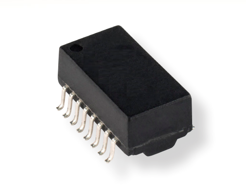
Product Details
Place of Origin: China
Brand Name: LINK-PP
Certification: ISO 9001,ISO 14001,UL,SGS,REACH168
Model Number: SM13072APEL
Payment & Shipping Terms
Minimum Order Quantity: 50pcs
Price: $0.05-$0.38
Packaging Details: 600 pcs/reel
Delivery Time: In Stock Ship Within 3 Days
Payment Terms: TT,NET30/60/90 Days
Supply Ability: 5KK/Month
Part Number: |
SM13072APEL |
Product Type: |
10/100 Base-T LAN Transformer |
Function: |
Ethernet Impedance Matching And Isolation |
Integrated Common Mode Choke: |
YES |
Mounting: |
Surface Mount (SMD) |
Package: |
16-Pin SMD / SOIC-style Package |
Construction: |
Potted |
TX Turns Ratio: |
1:1 ±2% |
RX Turns Ratio: |
1:1 ±2% |
OCL: |
350 µH Min. |
Isolation Voltage: |
1500 Vrms / 2250 Vdc |
Operating Temperature: |
-40°C To +125°C |
Qualification: |
AEC-Q200 |
Compliance: |
RoHS, IEEE 802.3 Compatible |
Part Number: |
SM13072APEL |
Product Type: |
10/100 Base-T LAN Transformer |
Function: |
Ethernet Impedance Matching And Isolation |
Integrated Common Mode Choke: |
YES |
Mounting: |
Surface Mount (SMD) |
Package: |
16-Pin SMD / SOIC-style Package |
Construction: |
Potted |
TX Turns Ratio: |
1:1 ±2% |
RX Turns Ratio: |
1:1 ±2% |
OCL: |
350 µH Min. |
Isolation Voltage: |
1500 Vrms / 2250 Vdc |
Operating Temperature: |
-40°C To +125°C |
Qualification: |
AEC-Q200 |
Compliance: |
RoHS, IEEE 802.3 Compatible |
The SM13072APEL is a high-reliability, surface-mount (16-Pin SOIC) discrete 10/100 Base-T Ethernet pulse transformer module engineered specifically for harsh automotive and industrial environments. Built with a fully potted construction, automated coil winding, and cable-side integrated common mode chokes, it provides continuous operation up to +125 °C, robust differential noise immunity (DCMRR: -35 dB), and dual dielectric isolation of 1500 Vrms / 2250 Vdc.
| Parameter | Specification | Engineering Significance |
| Ethernet Speed | 10/100 Base-T (Fast Ethernet) | Full IEEE 802.3 compatibility for adapter, hub, and LOM |
| Operating Temperature | -40 °C to +125 °C | AEC-Q200 qualified for automotive engine bay & harsh industrial |
| Turns Ratio | 1 : 1 (TX) / 1 : 1 (RX) ±2% | Symmetrical matching for voltage-mode & current-mode PHYs |
| Open Circuit Inductance (OCL) | 350 µH Min. (@ 100 kHz, 0.1 V, 8 mA DC Bias) | Prevents magnetic core saturation under direct DC imbalance |
| Dielectric Isolation (Hipot) | 1500 Vrms / 2250 Vdc (60 Sec @ 1 mA) | Exceptional protection against line surges, EFT, and ESD |
| Package Construction | 16-Pin SMD SOIC, Potted ("P") | Resists moisture ingress, severe thermal cycling, and vibration |
| Manufacturing Process | Automated Winding & Choke Assembly | High twist density per unit length; ultralow leakage inductance (0.5 µH) |
| Standard Packaging | Tape & Reel (13-inch reel, 600 pcs/reel) | Optimized for high-speed automated SMT pick-and-place lines |
All electrical specifications below are specified at 25°C unless otherwise stated.
| Electrical Parameter | Test Condition | Specification |
|---|---|---|
| TX Turns Ratio | 100 kHz, 0.1 V | 1:1 ±2% |
| RX Turns Ratio | 100 kHz, 0.1 V | 1:1 ±2% |
| Open Circuit Inductance (OCL) | 100 kHz, 0.1 V, 8 mA DC bias | 350 µH Min. |
| Leakage Inductance, TX | 100 kHz, 0.1 V, TD with TX shorted | 0.5 µH Max. |
| Leakage Inductance, RX | 100 kHz, 0.1 V, RD with RX shorted | 0.5 µH Max. |
| Winding-to-Winding Capacitance | 100 kHz, 0.1 V | 35 pF Max. |
| DCR, TD & RD | Chip side | 1.4 Ω Max. |
| DCR, TX & RX | Cable side | 1.0 Ω Max. |
| Insertion Loss | 1–100 MHz | -1.1 dB Max. |
| Return Loss | 1–40 MHz, 100 Ω load | -16 dB Min. |
| Return Loss | 40–100 MHz, 100 Ω load | -10 + 20 log(f/80 MHz) dB Min. |
| Crosstalk | 1–60 MHz | -40 dB Min. |
| Crosstalk | 60–100 MHz | -35 dB Min. |
| Common Mode Rejection | 1–60 MHz | -37 dB Min. |
| Common Mode Rejection | 60–100 MHz | -30 dB Min. |
| Differential-to-Common-Mode Rejection Ratio | 30 MHz | -35 dB Min. |
| Differential-to-Common-Mode Rejection Ratio | 60 MHz | -35 dB Min. |
| Hi-Pot | TD to TX / RD to RX, 1 mA, 60 s | 1500 Vrms / 2250 Vdc |
The published Bourns datasheet gives the same core electrical characteristics, including 350 µH OCL, 0.5 µH maximum leakage inductance, 35 pF maximum winding capacitance, -1.1 dB maximum insertion loss and 1500 Vrms isolation.
The open circuit inductance (OCL) is a key selection parameter for a 10/100 Ethernet transformer. SM13072APEL specifies a minimum 350 µH at 100 kHz, 0.1 V and 8 mA DC bias.
Engineers comparing alternative 10/100 LAN transformers should evaluate OCL under the same measurement conditions rather than comparing inductance values without test conditions.
SM13072APEL specifies a maximum 0.5 µH leakage inductance for both transmit and receive channels. Low leakage inductance helps maintain the intended high-frequency coupling characteristics of the transformer.
The specified winding capacitance is also limited to 35 pF maximum, which is relevant when evaluating high-frequency signal behavior and transformer compatibility.
The SM13072APEL integrates two symmetrical 1:1 channels (Transmit TX and Receive RX). The common mode chokes (CMC) are positioned on the cable side (Pins 14/16 and 9/11) to attenuate common-mode electromagnetic noise before it enters the PCB ground system.
While integrated RJ45 Magjacks are popular in consumer office equipment, SM13072APEL discrete magnetics are the preferred architecture for automotive and harsh industrial platforms due to three key factors:
Extreme Thermal Capability (-40 °C to +125 °C):
Commercial Magjacks contain internal plastic housings, LED inserts, and unpotted bobbins rated only to +70 °C or +85 °C. The SM13072APEL uses specialized automotive-grade potting epoxy and high-Curie-temperature ferrite cores, ensuring stable inductance even in high-heat engine bays.
High-Density Automated Winding:
Automated winding increases the wire pair twists per unit length. This precise winding control guarantees turns ratio accuracy (±2%) and drives leakage inductance down to an industry-leading ≤0.5 μH ensuring sharp pulse edge transitions and minimal jitter.
Flexible Layout for ESD & Surge Suppression:
Discrete transformers permit engineers to place high-energy ESD protection diodes (such as low-capacitance TVS arrays) directly between the external RJ45 connector and the transformer, isolating clamping currents away from the PHY.
The recommended PCB landing pattern should be followed when designing or reviewing the SM13072APEL footprint. In particular, engineers should verify the 1.27 mm lead pitch, 8.89 mm row-to-row center span, and the recommended 0.76 mm pad width before PCB release. The manufacturer's recommended layout specifies 7.10 mm and 10.50 mm pad-row dimensions for the inner and outer spans, respectively.